There are 10 types of people in this world; those who understand binary notation and those who don’t.
Some years ago I experimented with using a Ground Tuning Unit (GTU a.k.a. Artificial Ground) to replace radials/counterpoises on my field expedient vertical antennas. A GTU is simply a series L-C tuned circuit with a current sensor and meter to display the current. Wiring a variable capacitor in series with a variable inductance creates an “acceptance” circuit. It’s job is to maximize current flow in “the other half” of an antenna. If the ground current is maximized the current in the radiator is also maximized and the antenna efficiency is improved.
“No, that can’t possibly work. You need lots of radials; the more the better”
“Or you can replace all that wire on the ground with just 2 or 3 raised radials”
“An even better solution: remember that RF can’t see wire; it sees only a combination of Resistance – Capacitance – Inductance; aka Impedance. You can deceive RF into seeing a ‘perfect’ ground by providing the correct impedance in the ground path.”
“Ah, but you can’t do that on the antenna radiating element – a dummy load has perfect impedance but it doesn’t radiate!”
“That is very true, for a radiating element we really do need as much wire in the air as possible. But we don’t want the ground side to radiate. Maybe a dummy load would make a good counterpoise.”
“Aha! That’s a very interesting thought. Could we replace a radial field/counterpoise/Ground Tuning Unit with a simple high wattage, non-inductive resistor?”
“Hmmm“
Meanwhile, Back in the Lab at Ham Radio Outside Outside the Box …
The GTU works by providing a capacitive path to ground through a small metal plate or short wire. The capacitance and inductance are adjusted until maximum deflection on the current sensing meter is obtained.
A GTU is often built using a large air-core coil with multiple taps on the principle that somewhere along the coil there will be sufficient inductance to resonate with a large variable capacitor at the frequency of interest. But that approach results in a bulky device that is not appropriate for field deployment. I chose a different technique.
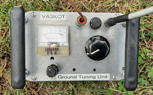
Using a simple spreadsheet I found combinations of inductance and capacitance that would be resonant on the bands on which I was planning to operate. At the time, my portable rig was a QRP radio that supports the 20m, 30m and 40m bands. So I built a GTU that would easily tune just those 3 bands. The result was a fairly compact, yet rugged device suitable for the rigors of field deployment.
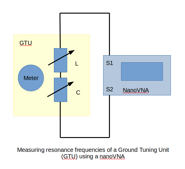
How can we verify that the GTU is doing its job? That question is solved using a nanoVNA in S21 mode and measuring the “logmag” (logarithmic magnitude), or decibel relationship between the signals at the 2 ports of the VNA. If the GTU is correctly adjusted, there will be a low dB reading on the VNA on resonant bands and a high dB reading for non-resonant bands. Result: the GTU was doing its job; the nanoVNA showed acceptance on 20m, 30m and 40m and rejection on all other bands.
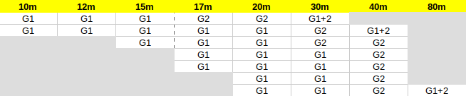
Needs change and new radio acquisitions with wider band coverage necessitated redesigning the GTU to cover all the bands from 80m to 10m. Once again it was decided to calculate the required inductance and capacitance needed to obtain resonance on every band of interest. This would be achieved by careful selection of the minimum number of inductors combined with whatever variable capacitor values I had in my junk drawer. Good air-spaced variable capacitors are becoming as rare as hens’ teeth so I work with what I have.
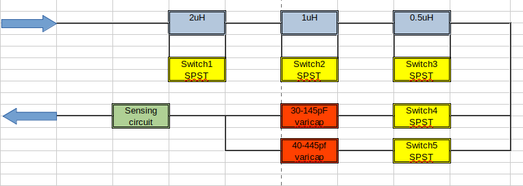
Another decision was made; instead of using a tapped coil and rotary selector switch, I borrowed a technique of binary inductance selection from an old QRP tuner project I built a long time ago. Careful design using a spreadsheet resulted in just five SPST (Single Pole Single Throw) switches being needed. Fortunately I have a box full of these switches from an auction purchase I made some time in the past. The spreadsheet showed that only 3 coils (0.5, 1 and 2 microhenries) would be needed. The variable capacitor has two gangs – 30 to 145pF and 40 to 445pF. Each gang can be separately selected, or both gangs can be used in parallel to combine the capacitance.
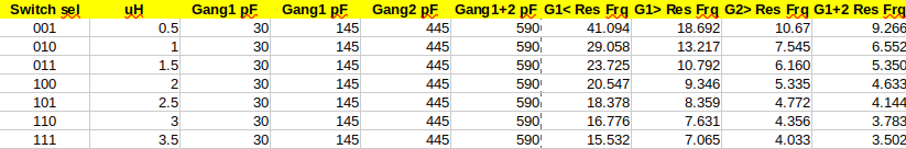
Gang1+2 (G1+2; 70-590pF). Lower values of capacitance are preferred to allow finer control.
The next step is to wind the coils, breadboard the circuit and verify that resonance can be obtained on each of the bands from 10m through to 80m. Then final construction can begin. When complete, the new Ground Tuning Unit will be featured in a later post. There are many projects lined up on the bench here at Ham Radio Outside the Box so please standby.
Thank you subscribers!
This blog is written without any commercial interest; no financial support is solicited and all expenses are covered entirely by the writer; that’s me John VA3KOT. So it is particularly gratifying when readers take the trouble to subscribe – thank you to all my subscribers. It is kind folks like you who make the effort of sharing these projects so worthwhile.
Help support HamRadioOutsidetheBox
No “tip-jar”, “buy me a coffee”, Patreon, or Amazon links here. I enjoy my hobby and I enjoy writing about it. If you would like to support this blog please follow/subscribe using the link at the bottom of my home page, or like, comment (links at the bottom of each post), repost or share links to my posts on social media. If you would like to email me directly you will find my email address on my QRZ.com page. Thank you!
The following copyright notice applies to all content on this blog.

This work is licensed under a Creative Commons Attribution-NonCommercial-NoDerivatives 4.0 International License.
