So many words have been written about the popular End-Fed Half-Wave antenna that you would think it would be “settled science” by now. For several years I have been building EFHWs according to accepted wisdom, but my inquisitive mind always seeks to question why they are built that way and could they be improved?
You could buy a commercial EFHW and just get on with making contacts, but there is not much to be learned that way. A ham radio license is a ticket to experiment and innovate. Maybe all the ways to improve the EFHW have been explored already, but just like baking a cake, there are many combinations of ingredients each yielding different results.
Because my principal interest in ham radio is operating outside in what I like to call the “Big Blue Sky Shack”, the latest build of the EFHW is not targeted toward optimum efficiency. Instead, the primary objective is to build a field expedient, rapid deployment antenna for QRP or QROp (20 watts) that will expedite logging 10 or more QSOs quickly and efficiently for a POTA activation.
The high impedance transformer
If a wire is half of a wavelength long there will be a high impedance at its ends. That much at least could be accepted as “settled science” (Recent discussion online suggests there are skeptics). So feeding a half-wave wire at its end creates a big impedance mismatch that must be corrected using a transformer.
Ohm is where the art is
Transceivers are usually designed for coax fed antennas with an impedance of 50 ohms. But what is the impedance at the end of a half-wave wire? The answer is we don’t really know. It is certainly a very high impedance, but is it 1500 ohms; is it 5000 ohms, or somewhere in between? The actual value depends on how, where and when it was erected. Even for a fixed installation at a home QTH, the impedance could change if it rained overnight.
Conventional wisdom says we should use a transformer with an impedance ratio of 49:1. That implies that the expected antenna impedance is 49×50=2450 ohms. But if the actual antenna impedance is really only 1800 ohms, the transformed impedance will be only 36 ohms. Is that a problem? Not really, the mismatch will be less than 1.4:1 – perfectly acceptable. Similarly, if the actual antenna impedance is 3500 ohms, the mismatch will be the same 1.4:1.
Turns, turns, turns
Okay, so we won’t challenge conventional wisdom on the transformer impedance ratio (remembering that the transformer turns ratio is the square root of the impedance ratio, i.e. 7:1). Now, how many actual turns are required? Once again, conventional wisdom has an answer to that question too. Wise men tell us we should use either 2 or 3 turns on the primary and either 14 or 21 turns on the secondary respectively. Which to choose? I believe the 3:21 turns ratio is probably required on the lower bands, e.g. 80m but that 2:14 is adequate for the higher bands. So, 2 turns on the primary and 14 turns on the secondary fits the requirements for our POTA field antenna. It will be used for the 40-10m bands, but principally 20m where most POTA activity can usually be found.
The core of the matter
Wise men say the transformer should be wound on a ferrite core made from type 43 material, but they disagree on what diameter core, and on how many cores are needed. If you are a QRO operator with a 1500 watt “boot” then go ahead and stack ’em high; 3 stacked FT240-43 cores should do it. But if you are a QRP operator, one of those tiny cores the size of a wedding ring is good enough.
It’s an open and shut case
Ferrite cores can overheat, so why put them inside a sealed enclosure? You may need to protect the transformer from the weather if it’s a permanent installation but for a field expedient antenna, let them breathe the air. I have never had a problem with cores overheating when operating low power for typically an hour or so and mine are not enclosed.
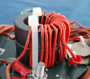
Wise men say the more cores the better the transformer. I am not entirely convinced, but there is merit to the argument that if more copper is inside the core, the magnetic linkage is better. On that basis I chose to build my EFHW transformer using 2 stacked FT140-43 cores. Stacking 2 medium size cores means that the coil windings are inside the core for twice the distance of a single core. I also built a purely QRP transformer using a single “wedding ring” core (I think it’s an FT80-43). As the ferrite toroid diameter decreases so does its thickness, so there is very little wire inside the very small core and it may be less efficient (although I have QSOd with it).
It ain’t over ’til it’s over
Who would have thought there are so many things to consider just in building a simple EFHW transformer? Well we aren’t at the finish line yet. Now we have to think about HOW to wind the transformer. I have come across 3 different ways. Wise men disagree again but one method seems to have attracted the most disciples.
Let’s do the twist
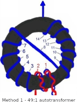
This first winding method creates an autotransformer. An autotransformer shares some of its windings between its primary and its secondary. In this method there is a slight variation on that idea. The primary and secondary windings are shorted together at the start, then the first 2 turns are tightly twisted together. The remaining 12 turns of the secondary include a crossover turn which serves only to bring the far end out on the other side of the core.
A second winding method merely places a tap after 2 turns on the secondary. I have tried this method but it didn’t work very well.

In both the above methods the start of the primary and secondary windings are shorted. The antenna then has a direct DC path through the secondary to the coax braid which can be used as a counterpoise.
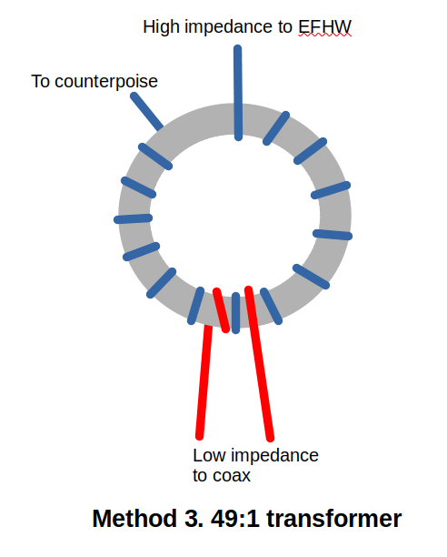
There is a third method that results in a conventional transformer with no DC connection between the primary and secondary. Instead, 14 turns of the secondary are wound on the core. A separate 2 turn primary is then wound, either elsewhere on the core, or on top of the secondary winding. I chose the latter since it probably improves the magnetic linkage between the windings. Another factor to consider here is that there is now no DC connection between the secondary and the coax braid. Can the coax braid still be used as a counterpoise?
A counterpoise … for an EFHW?
The feedpoint at the end of a half-wave wire is a high voltage point. This means there is very little current at the feedpoint, so do we really need a counterpoise? For QRP the answer is no, for higher power though a counterpoise is recommended to avoid RF in the shack. My own use case involves no more than 20 watts but since I chose the third winding method with no DC connection between the antenna wire and the coax, I added a short (~6ft) counterpoise wire connected to the opposite end of the secondary winding to the radiating wire.
Isn’t this just an Off-Center Fed Dipole?
I have seen this question raised online and the answer is no. It might appear to resemble an OCFD at first glance; we have a long wire fed 6ft from one end. But, an OCFD is a half-wave long, while this antenna is longer by 6ft. We are feeding our EFHW at a high voltage point. An OCFD is usually fed at around 1/3 of its length.
A capacitor on the primary?
Wise men say we should install a 100pF, high voltage capacitor in parallel with the primary. I have tried this but it didn’t seem to have any effect so I don’t use it any more.
A Common Mode Current Choke (CMCC)?
A Common Mode Current Choke is recommended (again, by the wise men) at the input to the transformer. This will prevent the coax braid being used as a counterpoise. Is it a good idea? Well, since I have a separate counterpoise wire on the transformer secondary then yes, I have installed a CMCC. As with any antenna, a CMCC at the radio end of the coax is a good idea to block RF induced from the near field reaching the radio.
Are we there yet?
We are nearly there, because there is yet another variant. Steve Yates AA5TB is a master of the End-Fed Half-Wave antenna. His matching device replaces the 49:1 broadband transformer with a parallel tuned circuit providing a match on just a single band. The broadband 49:1 will work on the primary band plus all its harmonics.
Oh wait, there’s a gotcha!
An End-fed Half-wave antenna is really only a half-wave on one frequency. Let’s say we design our EFHW for 40m. The length of the antenna wire will be a half-wave on 40m, a full-wave on 20m, 3 half-waves on 15m and 2 wavelengths on 10m. The conditions on a wire repeat every half wavelength but, instead of a single high current point (as is the case at the midpoint of the wire on 40m) there will be multiple high current points. Each high current point is a point at which maximum power is radiated and may lead to an irregular radiation pattern with multiple nodes and nulls. Yikes!
High Voltage Beware!
So maybe AA5TB had the best idea by choosing a single band EFHW. But let’s say we want to follow the other wise men and use a broadband antenna anyway. If we build an EFHW for 40m it will have a length of nominally 66 feet. The real length will be shorter due to the end effect; around 62 feet works for me. Often that’s too long for operating in a public space. We have to be careful because the far end of our wire is a high voltage point which potentially endangers other park users like children and dogs.
Exactly how high is the voltage at the far end of the antenna? Rough calculations show that for QRP it is only a little over a hundred volts; not enough to cause bolts of lightning but enough to give hams a bad rap if a child came in contact with our wire.
Use a loading coil and tail wire to shorten the antenna
We can instead build an antenna for 20m and electrically extend it for 40m using a loading coil with a tail wire at the end. In his YouTube channel, Tim G5TM proposed using a 35 microhenry loading coil with a short tail wire. The coil is attached at the end of the 20m EFHW and adds only about 6ft to the overall length of the antenna. I have used this technique in the past to extend a 40m EFHW to cover 80m. Because the coil/tail wire combination is much shorter than the equivalent full length wire, the Q is very high. I found out that trimming the tail wire for best SWR is a very delicate process!
This technique works very well but it does introduce another gotcha. Due to the end effect (shortening of a wire due to capacitive connection to ground) our 20m EFHW works out to about 31 feet long versus a calculated length of around 33 feet. But when we connect our loading coil, the 31ft radiator is now terminated and no longer subject to end effect – so it is now too short! In a comment on a prior post, Ham Radio Outside the Box reader David VE7EZM introduced us to the idea of using a short drop wire to compensate for this. Following David’s advice I attached a 2ft drop wire at the point where the 31ft wire meets the coil. The drop wire simply hangs in the air and restores the tuning on 20m.
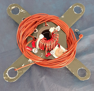
So What Have We Wrought?
The final rebuilt EFHW antenna comprises a 49:1 conventional transformer (per method 3). The radiating element is a 31ft wire and is attached to one end of the transformer secondary. The counterpoise wire is 6ft long (0.05 wavelengths on 40m) and is connected to the other end of the transformer secondary.
A 35 microhenry loading coil is attached to the end of the radiating element with a 2ft drop wire as described above. The tail wire is approximately 6ft long and is adjustable for fine tuning in the field.
This antenna will theoretically cover 40m, 20m, 15m and 10m. My principal bands of interest for POTA activations are 20m and 40m although I may stray onto 15m and 10m from time to time.
I am inclined to believe an EFHW will give better performance on its primary design band than on its harmonics, so I am entertaining the idea of using interchangeable radiating element wires for each band. I may post further on this topic after some experimentation.
Don’t believe everything you read on the Internet
Abraham Lincoln
End-Fed Half-Wave antennas are a controversial topic; some operators love them, others do not; everybody has an opinion. My own idea is to use my EFHW for field portable use where convenience overrides perfection. As always, I am no expert (x is an unknown quantity and spurt is a drip under pressure) so please excuse and maybe correct any errors. If you have any ideas to add to this discussion please add them to the comments below.
I found the following article very helpful in understanding the EFHW; I recommend reading it:
Help support HamRadioOutsidetheBox
No “tip-jar”, “buy me a coffee”, Patreon, or Amazon links here. I enjoy my hobby and I enjoy writing about it. If you would like to support this blog please follow/subscribe using the link at the bottom of my home page, or like, comment (links at the bottom of each post), repost or share links to my posts on social media. If you would like to email me directly you will find my email address on my QRZ.com page. Thank you!
The following copyright notice applies to all content on this blog.

This work is licensed under a Creative Commons Attribution-NonCommercial-NoDerivatives 4.0 International License.
Discover more from Ham Radio Outside the Box
Subscribe to get the latest posts sent to your email.

Thank you for this interesting post. Would like to know why you went for 49:1 instead of 36:1 as suggested in the article you recommend above by the two Bob’s. Is it because the 49:1 design was more portable?
Cheers.
LikeLike
Thanks for your contribution to the conversation. Some sources do suggest changing the turns ratio for different bands. Some even recommend using different ferrite mixes for different bands. I chose to settle on the standard 49:1 for my field portable EFHW because every time I erect it conditions such as height, soil conductivity etc are different for each location. It does impact efficiency, but that’s a compromise we have to accept out in the field.
I actually rarely use an EFHW with a high turns ratio impedance transformer now. There are better solutions, such as an L-network detailed elsewhere in my blog.
LikeLike
Really enjoy your thoughts; thanks for putting in the work and sharing it with us!
72/72 DE KT6L
LikeLiked by 1 person