
The Double Bazooka antenna is a very old idea first developed in 1944 for radar that has been modified for amateur radio use. I was alerted to its advantages by Ham Radio Outside the Box reader “Trippy” Brown AC8S who lives in the state of Michigan across mighty Lake Huron from my home town in Canada.
As an aside, Michigan is about a hundred miles across the lake from where I live in Ontario. But 3 or 4 hours south the Blue Water international bridge links Ontario with Michigan at the entrance to the St Clair river.
There are quite a few references to the Double Bazooka online, but as Abraham Lincoln is often quoted as saying “don’t believe everything you read on the Internet”. I have a personal guideline when reading about antennas online “don’t tell me what you believe; show me the math”. The math will be presented later in this post so you can judge for yourself. Errors and myths tend to spread like a virus. Don’t even believe everything you read here on Ham Radio Outside the Box, I check everything very carefully but I am not infallible.
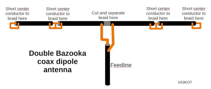
The whole antenna can be built from a length of coax built in three sections – a center section that acts as an impedance transformer, and two “tail” sections that extend the antenna length to a full half wave. It can be constructed from inexpensive coax like RG58. Trippy, AC8S, advises to avoid coax with a foam dielectric and recommends choosing cable with a polyethylene dielectric instead. The tail sections can be made with simple pieces of ordinary wire, twin lead, ladder line or coax. I discovered one advantage of building the whole antenna out of coax – it can be neatly coiled when not in use.
Several advantages to the Double Bazooka have been touted. It is said to be less prone to noise pickup than wire dipoles. It is also claimed to have broader bandwidth (probably due to the fact that the coax braid is doing the radiating. “Fat” conductors have inherently wider bandwidth than thin conductors like wire).
So what about the disadvantages? Number one, in my opinion, is its significantly enhanced response to gravity compared to a wire dipole. In plain language, it’s bloomin’ heavy!
Construction can be a little tricky so caution is advised. A sharp knife and a high temperature soldering iron are good tools to have for this antenna construction. Careful attention to the dimensions is required. Over zealous snipping of the antenna ends for fine tuning is to be avoided. Apart from that, experienced antenna builders with good eyes, a steady hand and the appropriate tools should have no trouble building one.
I decided to build one to check it out for myself. I don’t have steady hands or good eyes any more, but my expensive new Weller WE1010 soldering station was a good investment. I expect it to outlive me! I bought a set of tips for it so – theoretically – I can tackle any job from fine tracks on printed circuit boards to coarser work like building coax cables. But like I said, I don’t have steady hands or good eyes any more.
If you are an experienced antenna builder you won’t need detailed build instructions. If you are an inexperienced builder and you are patient and careful, this build will not be too challenging.
Building the center section
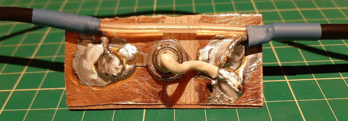
Using the math equations given below, select the correct length for the band you want to use. Now remove a couple of inches of the insulation from the center, then cut and separate the braid to form the connection point for the feedline. Most sites suggest soldering the coax feedline directly here. I used the Sinatra method (“I did it my way”). I cut a small piece of copper clad board, then using my Dremel tool, I cut connection traces in the copper cladding. I then mounted a BNC female panel connector and soldered the connection points. Doing it this way I can connect a feedline of any length I choose, and the antenna itself can be easily coiled (using the “over-under” technique) when not in use.
BNC stands for "Bayonet Neill Concelman" a cable connector developed for the military in World War 2. Perhaps I shouldn't have mentioned this in case security service bots detect the words "bayonet", "bazooka" and "war" in this post. Just a moment, I hear a loud knock at the door ...
Next step; at each end of the center section, short the coax braid to the center conductor. The center section is now complete. It forms an impedance transformer and presents a nice wideband low SWR at the feedpoint.
Building the Tail sections
Using the math equations given below, select the correct lengths for the band you intend to use. Now short the coax braid to the center conductor at each end of the two tail sections. I built my two tail sections precisely according to instructions. When I set up the antenna for testing the SWR was a little higher than expected. I brought it down to around 1.2:1 by cutting small pieces off each end of the two tail sections. That, of course, meant the center conductor was no longer shorted to the braid at the antenna ends. That didn’t seem to be a problem though. The braid does the radiating, the center conductor (which runs the whole length of the antenna) is already shorted to the braid at the other end of the tail sections where they join the antenna Center Section.
NB: The tail sections can also be made with a just a simple piece of wire. In fact, I initially built my Double Bazooka this way. I switched to coax for the tail sections to create a uniform appearance along the entire length of the antenna.
Connecting the Center Section to the Tail Sections
This is the part where a good hot soldering iron comes in handy. When the coax braid is shorted to the center conductor at various points along the length of the antenna, the combined conductors are quite fat. Now we have to securely connect two of these fat conductors together. I used a pair of “helping hands” (two alligator clips attached to a steel bar, mounted on a metal base) to hold the two sections together while I attacked them with my Weller iron and a generous amount of solder from a large spool of Ersin Multicore solder I picked up at a charity store.
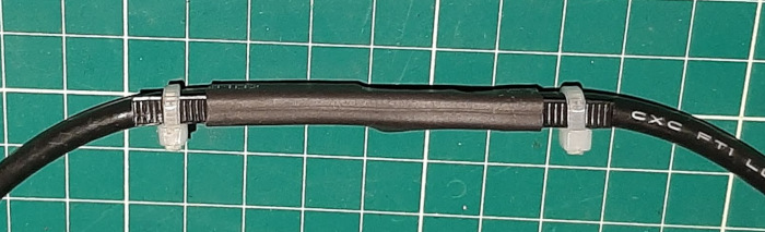
Remember I said this is a heavy antenna? That means there will be considerable strain on the points where the Center Section is spliced to the two Tail Sections. To reinforce these splices I used zip ties and shrink wrap as can be seen in this picture.
The backyard antenna test range
Now for the part where the electromagnetic energy hits the ether. I coiled up my newly built Double Bazooka antenna and loaded it onto a forklift truck for transportation to the test range. Okay, I’m kidding, just wanted to emphasize that it’s a bit of a heavy beast. I have a 16 feet high pole made with bits of two Crappie fishing poles that is very strong. I hauled the Double Bazooka and its attached coax feedline up on the pole. I swear I heard the pole scream with pain. This wasn’t going to work.
Plan B. I broke out a few sections of surplus fiberglass US military camouflage netting support poles. These poles come in sections each four feet long and they are built strong; I mean very strong (as long as you don’t stack too many of them without guy wires, or they will break where they join. This pole stood whistling a happy tune while effortlessly supporting the weight of the antenna and feedline.
Does it QSO?
I think I have mentioned this before. I make the QSOs; the antenna just sits there grinning at the sky. But yes, QSOs were made. I had built a 20 meter version. I hooked it up to my venerable old Yaesu FT-897 radio powered by a Bioenno Lithium Iron Phosphate battery. I keyed up and fired a whopping 20 watts of RF radiation into the antenna. Another sidenote is relevant here. My wire dipoles are made with thin gauge wire because it is very light and easy to carry around in a backpack. They were built for QRP operations. An antenna made with coax can handle considerably more power. Maybe not legal limit, but 100 watts should be no problem at all.
My first impression was, just like the claims I have read said, it seemed to be a very quiet antenna. The K-index was at 3 and the solar wind was north of 500 km/s. Conditions were predicted to be “unsettled”. I decided to hunt a few CW POTA activators. I was able to work every station I called so that gave me a favorable impression of my Double Bazooka at its first trial.
Is it better than a wire dipole?
Frankly I haven’t tried an A/B test to answer that question. All I can say at this stage is that it certainly beats a wire dipole when it comes to not being blown away in the wind! And we often get some pretty darn good winds coming off the vast expanse of water that is Lake Huron. The first trial has given me a good enough impression of the Double Bazooka to want to take it out into the field next spring. Snow is in the forecast soon for this part of Ontario and that limits my enthusiasm for backpacking down trails to play radio. It’s almost time to hibernate for the next few months.
So show me the math!
Ok, ok, here it is:
Center Section length = 492 times VF divided by frequency
Tail Section length = (468 minus (492 times VF)) divided by (2 times frequency)
Where VF is the coax velocity factor and frequency is in MHz
Why did I write out the equations in this longhand way?
Trippy AC8S taught me to how to write out equations using words. You see Trippy is blind and relies on a screen reader to follow along with what is on his screen. Screen readers become confused with mathematical expressions written the usual way.
Trippy is an intelligent, very energetic ham who is bursting with enthusiasm for experimenting with antennas. He has many very interesting ideas to share. But, being blind, he has very limited ability to actually build any but the simplest of antennas. He and I have exchanged many emails and I enjoy sharing ideas with him. Trippy needs somebody to help him. If you are located anywhere near Port Huron, Michigan, and are willing and able to assist him in any way, please get in touch with him directly. Trippy’s contact details are good on QRZ.com.

Help support HamRadioOutsidetheBox
No “tip-jar”, “buy me a coffee”, Patreon, or Amazon links here. I enjoy my hobby and I enjoy writing about it. If you would like to support this blog please follow/subscribe using the link at the bottom of my home page, or like, comment (links at the bottom of each post), repost or share links to my posts on social media. If you would like to email me directly you will find my email address on my QRZ.com page. Thank you!
The following copyright notice applies to all content on this blog.

This work is licensed under a Creative Commons Attribution-NonCommercial-NoDerivatives 4.0 International License.
Discover more from Ham Radio Outside the Box
Subscribe to get the latest posts sent to your email.


I don’t see the logic behind having the end sections be coaxial as well. Could there be any purpose other than just adding weight? What if I were to connect a straight wire here instead? de TA1DX
LikeLike