
I came across an interesting antenna design recently and I just had to build one to try for myself. The original version is a commercial antenna, built for the Australian military, called the Bushcomm Mil-1. The manufacturer claims it presents a low SWR from 3 to 30 MHz without a tuner. It is quite an expensive antenna but it is built for the military and is required to be considerably more rugged than needed by the average amateur radio operator. The physical specifications are really quite impressive, but what about its performance?
The Mil-1 is 28 meters long and requires a 9:1 impedance transformer and a 470 ohm load resistor. I could not find those values specified in any manufacturer’s documentation but a YouTube video by Pete M3KXZ provided the build instructions. This is how the hambrew version is constructed:

I built my own 9:1 impedance transformer using a type 43 ferrite toroid (25.4 mm diameter) wound with the colored conductors from some old telephone cable (remember when telephones were connected by wires?). I chose to configure mine so that it presented a balanced line interface to the antenna and an unbalanced interface to the coax feedline. I suppose it could be called a 9:1 balun. The original manufacturer calls it a balun so I chose to go with that. I could also have configured it as a 9:1 unun. Is the antenna balanced or unbalanced? It appears unbalanced so would an unun have changed the results I got when testing it? I may try that to find out at a later time. TechTip #5 here on Ham Radio Outside the Box discusses the differences between impedance transforming ununs and baluns.
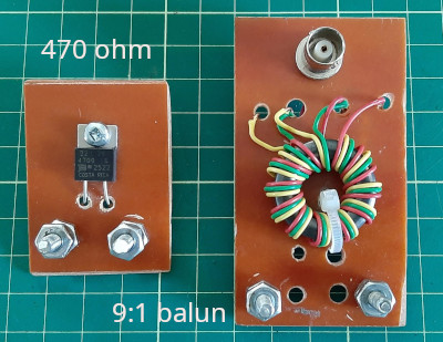
The load resistor has to be a high wattage non-inductive type. I generally operate QRP in the field so I chose a 20 watt thick film resistor from Mouser.
Both devices were built on small circuit boards made from single sided copper plated material. I cut the tracks on the boards using a Dremel tool. The result wasn’t elegant but only took a couple of minutes to complete, and no nasty chemical etchants were required.
Note that for higher power use a higher wattage resistor would be needed (also available from Mouser). Also, a larger toroid core would be required for the 9:1 device.
How did the Ham Radio Outside the Box clone of the Mil-1 perform?
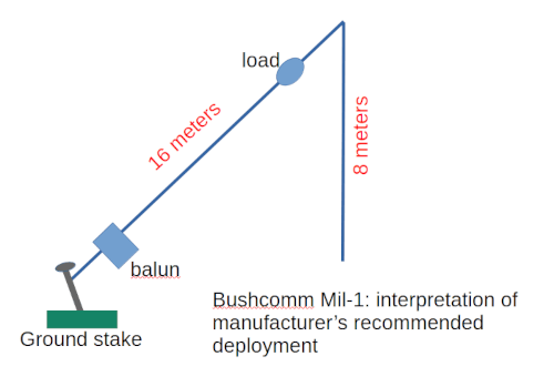
I erected my hambrew clone as an inverted-V supported at around 9 meters on a telescoping fiberglass pole. Later I discovered, in a video from John VK4BZ, that the manufacturer has a different suggested way of erecting their antenna, as shown in the diagram below.
Pete M3KXZ erected his Mil-1 clone at an NVIS height of only 2 meters above ground and was successful in making QSOs with it.
I modeled all three configurations in EZNEC and determined that the manufacturer’s recommended configuration may have the best performance of all three. The manufacturer’s original drawing describes the 8 meter vertical wire as a “coupling section” which may imply it has more to do with the antenna’s tuning than its radiation pattern. That’s my interpretation anyway.
But back to Ham Radio Outside the Box’s antenna test range in a backyard in Owen Sound, Ontario in the fall of 2026. How was the SWR across the bands? Actually I was pleasantly surprised by the low SWR on the lower bands. In fact from 80 m through 20 m the SWR was below 1.5:1. However, above 20 meters the SWR was unacceptable without a tuner. And, of course, a low SWR does not automatically indicate an efficient antenna.
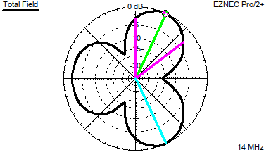
I made a couple of QRP CW QSOs with this fascinating antenna. A station to the west of my QTH gave me a 599 signal report, but another station to the south gave me only a 439 RST. The EZNEC model gave me a good hint as to why there was a big discrepancy between the two reports. The radiation pattern on 20 m breaks up into three nodes. If the azimuth to the station at the other end of the QSO is not within any of these nodes then, of course, I will be lucky to make the contact at all.
NB: This radiation pattern occurs with the manufacturer’s recommended configuration. With an inverted-V configuration the pattern is a little more forgiving but still quite directional.
I modeled the radiation pattern across all the bands and found the maximum signal strength varied all around the compass. Some of the higher bands even showed an unexpected maximum signal strength at high elevation. Clearly, if the model is accurate, the Mil-1 clone cannot be used reliably across all HF bands. The only consistent radiation pattern came on the 40 m and 80 m bands where the Mil-1 would be used primarily for NVIS operation. But, that’s not the whole story.
How about the antenna’s gain?
Now we are getting closer to the devil’s bargain that underlies tunerless low SWR across all HF bands. On the 20 m band the antenna has close to unity gain. Since I won’t be using this one on the higher bands (due to the bizarre radiation pattern variations) I am not concerned about the gain there. On the lower bands modeling suggests the antenna is lossy. Using the recommended deployment configuration a loss of over 6dB is expected on 80 meters. Perhaps the military sees this as an advantage. They may be more interested in short range communications between, for example, a Forward Operations Base and a Command Post. Any signal reaching beyond that range may be subject to eavesdropping by an enemy. At least that may have been true before advanced encryption techniques were introduced.
Could the Mil-1 still be useful as an NVIS antenna? Yes, I think so. At just 28 meters in length it is shorter than an 80 m dipole which is 40 meters long. In the recommended configuration the ground footprint is much smaller than a dipole. A dipole has better gain than the Mil-1 so it’s a matter of choice. In the real world any antenna is a good antenna if we can make QSOs with it!
The precise purpose of the load resistor is unclear. If the load resistor is omitted the gain improves significantly. But I am sure the designers of the original antenna had their reasons for including it. Perhaps, in further evaluation tests out in the backyard I will try eliminating the load resistor. The antenna may then require a tuner (I’m guessing at this stage) and, if that is the case, the insertion loss of a tuner will almost certainly be less than the insertion loss of the load resistor. When you make bargains with a fallen angel there is always a price to pay!

Help support HamRadioOutsidetheBox
No “tip-jar”, “buy me a coffee”, Patreon, or Amazon links here. I enjoy my hobby and I enjoy writing about it. If you would like to support this blog please follow/subscribe using the link at the bottom of my home page, or like, comment (links at the bottom of each post), repost or share links to my posts on social media. If you would like to email me directly you will find my email address on my QRZ.com page. Thank you!
The following copyright notice applies to all content on this blog.

This work is licensed under a Creative Commons Attribution-NonCommercial-NoDerivatives 4.0 International License.
Discover more from Ham Radio Outside the Box
Subscribe to get the latest posts sent to your email.

