As I mentioned in the last post on Ham Radio Outside the Box, I received a surprise package in the mail from Tim KQ4TQ in Georgia. Tim sent me his build of a mini Ground Tuning Unit (GTU) that is simpler in design than the one I built. Tim’s design is a single inductor of 3 microhenries wound on a T82-6 toroid, in series with a 10-355pF polyvaricon. The polyvaricon used in my original Mini-GTU had a maximum capacitance of only 160pF (I extracted it from a charity store AM/FM radio).
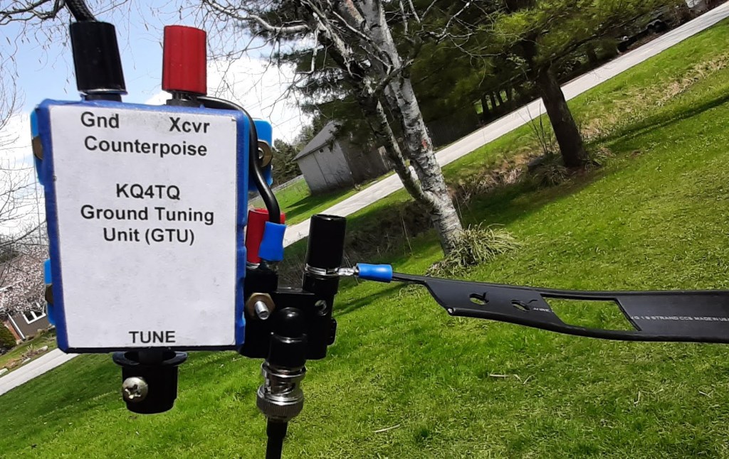
Tim’s GTU was quickly deployed out in the Ham Radio Outside the Box antenna test range (my backyard in Owen Sound, Ontario) for a full evaluation. Tim warned that tuning is very sharp and a steady hand is needed to get the best setting. My aging hands are definitely not as steady as they used to be but I found it was actually quite easy to tune.
The original Mini GTU versus the KQ4TQ GTU
The original Mini GTU recently described here on Ham Radio Outside the Box has 4 inductors, each with a shorting switch, in series with a polyvaricon. The purpose of the switches is to enable binary selection of inductance between 0.5 and 7.5 microhenries. By experiment I had discovered that easiest tuning is obtained when the inductance is low (and, of course, higher inductance introduces ohmic loss). So the objective was to binary select an inductance, starting at the lowest value (0.5uH), adjust the capacitance by rotating the polyvaricon knob and measuring the effect on the antenna’s SWR. Then, if an acceptable SWR is not obtained, add more inductance and measure again. In practise it was discovered that a value of 2 or 3 microhenries works for most of the bands tried. By contrast Tim’s GTU, with its single inductance of 3uH simplifies the tuning procedure. Actually, either design works equally well although the original Mini GTU with 4 inductors can also be deployed as an L-match with precision inductance selection.
I reluctantly felt the need to repackage Tim’s GTU in order to implement a couple of design enhancements. When I nervously advised Tim of what I had done he graciously accepted the ideas. Here are the changes:
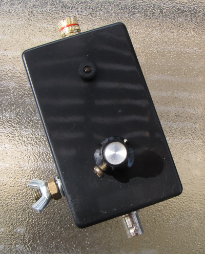
The original enclosure (see picture earlier in this post) required an external BNC to binding post adapter which looked clumsy. My first mod was to build Tim’s GTU into a small plastic box from the “River in Brazil” company. An LED and sensor circuit was included to give a visual indication of the best setting of the GTU.
I chose a high brightness LED since the device will often be used in bright sunshine. We do actually get bright sunshine during the brief interval between snow storms that we call “summer” here in Ontario. As I write this my home air-conditioning is actually running for the first time – but we will back to heating again in a couple of days.
A quick reminder about the function of a GTU. A GTU is a ground tuner, it’s purpose is to tune a compromise counterpoise to increase its current flow. Increasing the current flow in the counterpoise allows increased current to flow in the radiator portion of the antenna.
Why use a compromise counterpoise? It is sometimes necessary when setting up in a very restricted space location.
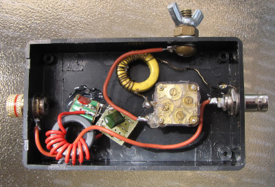
Here is where I went “outside the box” in my thinking. It might have been logical to place the current sensor in the ground circuit. But the end objective is to improve current flow in the radiator, so why not just place the current sensor in the radiating element path? In fact, that is what I did. If you look at the internal picture of the repackaged GTU you will see a wire passing through the inductor (red winding), connecting the binding post at the left end (where the radiator wire connects) to the BNC at the right hand end.
Two small circuit boards are visible. The one on the left contains the high brightness LED, recycled from an old defunct SLA battery box. The other small board contains a Germanium diode, RF bypass capacitor and current limit resistor for the LED. The toroid with the red coil turns is an FT82-43; it forms a 10:1 transformer used to sense the level of current flowing in the radiator path which is then displayed by the LED.
So does it work?
This is that rubber hits the road moment. Appropriate since I just had the winter tires taken off my truck. Those tires, dual-range 4-wheel drive and an economical yet powerful V8 engine got me out of more than one deep snow drift last winter. But, anyway, back to the topic in hand, does it work?
Mike W4AEE recently commented: “why are you using a capacitive coupling plate on top of lossy soil? I don’t understand why you would want to put this huge amount of loss in the antenna system. You’re forcing exchange currents between the vertical element ground system to try to flow through a high resistance that’s in series with the circuit. A single counterpoise wire thrown out on the ground would be better than that.”
Mike has a valid point. But, of course, the objective was not to engineer a perfect antenna the Physics Department would endorse. The original design called for a hiking antenna that can be rapidly deployed in a small clearing in the woods. There are many locations I venture into where it simply isn’t possible to lay out an efficient set of radials. A capacitance plate on the ground is indeed a compromise – as was revealed in a recent post here when I rejected the magic carpet ground plane idea as being inefficient. I tried alternative grounds. Here are a couple of them:
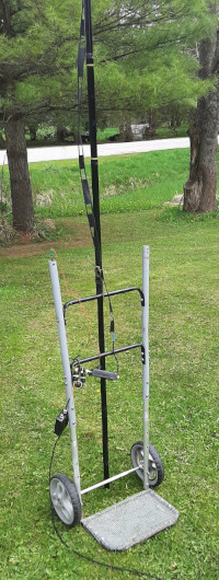
First up was a small hand cart I built specifically for ham use. There is a DC path all the way through the aluminum tubing to the steel mesh platform at the bottom. The mesh platform is a capacitive plate for use with a GTU.
At the top you can see the linear-loaded 20m band radiating element made from commercial 450 ohm window line. Did the LED glow when RF was applied? Yes sir and the measured SWR was 1.3:1. That’s good isn’t it? No, I’ll explain in a minute.
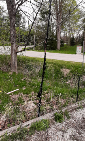
Next up was a 22ft long steel wire marker fence along the side of my driveway. The 3ft high fence was built as a guide when snow piles up in the winter. It didn’t work too well the last couple of winters when it disappeared beneath the snow! Just about the same RF result was obtained as with the hand cart.
Heck, I made plenty QRP CW contacts so why wasn’t I happy with the magic carpet or these ideas? The answer is very simple and is contained in the popular saying “SWR makes you stupid”. Yes, the SWR was well under 1.5:1 … BUT … even with a tested resonant linear-loaded radiating element, the overall antenna including the tuned ground circuit, was not resonant. The best impedance I could obtain was 42-j14.8 ohms. A resonant antenna is purely resistive, i.e. there is no reactive component – ideally 50+j0 ohms. Resonance results in the maximum energy transfer between the transceiver and the antenna.
LESSON LEARNED: A Ground Tuning Unit can transform a high impedance ground to a low impedance that is acceptable to a transceiver. But a transceiver cannot discriminate between a low SWR and a purely resistive load. Low SWR does not necessarily imply resonance.
Just a cotton pickin’ New York minute …
Of course an antenna doesn’t have to be resonant to radiate well – it can be adjusted to resonance by means of a “tuner” (technically an impedance matching unit). So, I added a tuner – I used my “Old Barebones” ham-made Z-match, located at the antenna end of my coax cable. That worked. It brought the antenna system into resonance, even with just a few feet of wire thrown on the ground and tuned by a GTU.
Two is too many, one is good
You heard the old saying “two is one, one is none”. Well it doesn’t apply here. Having two boxes dangling from the antenna is ungood. One box is the GTU and the other is a tuner – one too many. My next project will be to combine those two functions into a single small box. Tim KQ4TQ tried to tell me that already; I should have listened.
We’re getting close to ham hiking heaven; stay tuned.

Help support HamRadioOutsidetheBox
No “tip-jar”, “buy me a coffee”, Patreon, or Amazon links here. I enjoy my hobby and I enjoy writing about it. If you would like to support this blog please follow/subscribe using the link at the bottom of my home page, or like, comment (links at the bottom of each post), repost or share links to my posts on social media. If you would like to email me directly you will find my email address on my QRZ.com page. Thank you!
The following copyright notice applies to all content on this blog.

This work is licensed under a Creative Commons Attribution-NonCommercial-NoDerivatives 4.0 International License.
Discover more from Ham Radio Outside the Box
Subscribe to get the latest posts sent to your email.
