Ham Radio Outside the Box receives quite a lot of email every week from readers with questions, comments and suggestions. One such email came about as a result of an article in the outstanding newsletter from the Surrey Amateur Radio Club called the Communicator. The editor of the Communicator is Canadian Amateur Radio Hall of Fame member John Schouten VE7TI. John approached me some time ago to see if I would be willing to be a regular contributor to the Communicator. I readily accepted and I am indebted to the Communicator for publishing a regular series of posts from this blog to the Communicator’s international readers in over 150 countries.
A recent article in the Communicator triggered an email from Guy VA7GI and that sparked a chain of correspondence beginning with a request for more details of the Ground Tuning Unit featured in recent posts on this blog. Then Guy suggested I conduct a test to compare a GTU combined with a Faraday cloth (“Magic Carpet”) capacitance plate on the ground, to a regular set of radials. That sounded like an interesting challenge so I set up a test antenna out in the backyard to find out how the two compared.
An old, bruised and battered, long retired MFJ 20m telescopic whip was mounted on a tripod and promptly caught a gust of wind which sent it crashing to the ground. Fortunately it just missed a large birch tree and landed softly on the grass. More bruises! It was re-erected and secured with cordage to prevent any further falls. Then a 17ft raised wire counterpoise was attached via an RF current sensor.
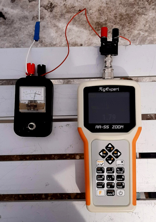
RF was applied to the antenna by a RigExpert antenna analyzer and a strong deflection was observed on the current sensor. The meter reading was set to mid-scale by adjusting the instrument’s sensitivity control. Now it would be possible to determine whether the current through the GTU/Faraday cloth was higher or lower than the current passing into the wire counterpoise.
Next step; the counterpoise wire was disconnected and the GTU was attached with a wire to the Faraday cloth on the ground. Once again RF was applied and the relative current was observed on the meter. NB: the current sensor does not measure absolute current values; its job is only to compare relative values. I expected the GTU/Faraday cloth ground arrangement to compare favorably with the wire counterpoise, after all I had made multiple contacts with this arrangement. But, to my surprise, the ground current was now lower than the wire counterpoise result.
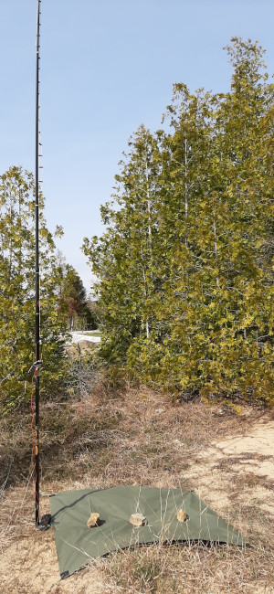
My “magic carpet”, made of Faraday cloth ordered from the company named after a Brazilian River, was a purchase made for the purpose of experimentation. To its credit, it served its purpose, but I had some reservations about its suitability for field portable radio operations. The first time I laid it out on my backyard lawn was during a day of bright sunshine. I was dazzled by the sunlight reflected from its surface. Those reflections were probably observable from Earth orbit and certainly detracted from the stealth of a field installation. Stealth was restored with a coat of dark green, non-reflective spray paint.
The outdoor environment challenged the installation with another trial – wind. The wind had already laid the antenna whip down, now it blew under and around my one square meter of Faraday cloth making it difficult to secure it to the ground. No spring gusts were going to defeat this scientific experiment, so reinforced grommets were attached to each corner of the cloth which was then tightly and securely held in its place with tent stakes.
After a few deployments the edges of the Faraday cloth began to fray and were secured with Gorilla tape, but the non-reflective paint was beginning to crack where the magic carpet was folded between uses. And then it failed the current test!
The image shows the Ham Radio Outside the Box Linear-Loaded Monopole with Magic Carpet deployed along the shore of Lake Huron during a recent OOTA activation. No, that’s not a typo, OOTA is “Out On The Air”. Check it out online.
So is the Magic Carpet idea dead in the water? Guy VA7GI had another suggestion: “I have two friends with ham rigs on sailboats. They each use a backstay with insulators as a vertical antenna. You’d think with a saltwater ground they have the perfect ground plane. But it’s not that simple. They use folded copper wire in the bilge for a ground. They don’t want to drill a hole in the hull or dangle a wire near the prop. Alternatively, they could use Faraday cloth and your GTU. I bet that’d make a huge difference, especially for trans-ocean sailing.”
So magic carpet rides on the wayward wind are grounded, at least for now. My home QTH is surrounded by the Great Lakes so maybe the the idea of a “floating ground” is worth exploring?
The magic carpet is grounded, but not the GTU!
In a later email Guy VA7GI said: “My intuition is that most verticals have compromised radials, placed wherever convenient or possible. Perhaps all vertical antennas would benefit from a GTU.” On the first point Guy may be right. There is a lot of discussion online about the placement of radials. On the ground, or raised above ground? Positioned to direct an antenna’s radiation in a particular direction? Or spread evenly to enhance the widest ground coupling? And, of course, how many radials?
Guy’s second point: “Perhaps all vertical antennas would benefit from a GTU” got me thinking. Could that idea be of benefit in implementing a limited footprint, vertical quarter-wave field antenna? How does a Ground Tuning Unit work? It resonates a capacitive ground path which increases the current in “the other half” of an antenna. That is an idea worth exploring, so a further test was conducted.
A new, improved linear-loaded monopole was erected. The ham-made ladder line previously used has been replaced with a slightly longer (11.5ft) section of 450 ohm commercial window line. When erected as a quarter-wave vertical worked against a GTU tuned counterpoise, the length is not critical within certain restraints because the electrical length of “the other half” is adjustable by the GTU. A shorter radiating element with a longer counterpoise works, as does a longer radiator with a shorter counterpoise. The antenna impedance changes, but unless taken to extremes, it remains close enough to keep the SWR presented to the transceiver within acceptable limits.
This new test was designed to discover whether a GTU could resonate short raised radials sufficiently well to make the antenna an efficient radiator. This arrangement would get a passing grade if the current through the GTU/short radials combination matched the current passing through full-length radials. It didn’t work out too well with the Faraday cloth so I was skeptical about the outcome of this test.
My 11.5ft linear-loaded monopole was paired with two raised radials each 16.5ft long but with links at 11ft and 13ft. Once again, the current was monitored with the full-length radials and set to mid-scale on the meter as a benchmark. Then the radial links were opened at the 11ft point and the GTU was adjusted for maximum current. This time there was a different outcome. The current matched the result obtained with the full-length radials. So Guy – you were right!
Further tests will be conducted with even shorter raised radials to determine whether the current can be maintained with a minimum possible ground footprint. The objective is to design a simple pedestrian portable antenna that can be deployed in a limited space environment such as small clearings in the woods.
The man from the future
Another project remains on the slate and that is the idea of using a helically wound radiating element as suggested by a reader in New Zealand (the “man from the future” – New Zealand is 16 hours ahead of the Eastern Time Zone). Ham Radio Outside the Box will cover that in a later post.
Meanwhile a package arrived in the mail
I was very pleased to receive a package in the mail from Tim KQ4TQ. Tim sent me a GTU he had built himself and asked me to evaluate it. Tim’s GTU is a slightly different build to my own and I will certainly evaluate it fully and report back here soon. Thanks Tim!
Thanks to all Ham Radio Outside the Box subscribers
I put a lot of work into preparing posts for this blog, but it is a labor of love. I seek no financial return, nor will I accept any; this is a hobby not a business. My motivation is to stimulate discussion and learn from experiments and the feedback of other hams. So it was gratifying when WordPress informed me recently that Ham Radio Outside the Box has now surpassed the modest level of 1000 subscribers. Knowing there is a steadily growing interest in the content generated here makes all the work worthwhile. Thank you!

Help support HamRadioOutsidetheBox
No “tip-jar”, “buy me a coffee”, Patreon, or Amazon links here. I enjoy my hobby and I enjoy writing about it. If you would like to support this blog please follow/subscribe using the link at the bottom of my home page, or like, comment (links at the bottom of each post), repost or share links to my posts on social media. If you would like to email me directly you will find my email address on my QRZ.com page. Thank you!
The following copyright notice applies to all content on this blog.

This work is licensed under a Creative Commons Attribution-NonCommercial-NoDerivatives 4.0 International License.
Discover more from Ham Radio Outside the Box
Subscribe to get the latest posts sent to your email.

Hi John-I did a POTA activation on Tuesday, and your mention of ‘wind’ was certainly appropriate. My wife had urged me to take a break from outdoor chores and simply enjoy the day. The weather was sunny but the wind was considerable. Call me a wuss, but I usually draw the line at 30 mph gusts.
I run a 17′ Chameleon whip atop a 6-foot aluminum mast. Two quarter-wave radials complete the picture for a 20-meter Inverted-Y. Once the mast and whip were in place, I watched with some alarm as its 25-pound weighted base tipped about 20 degrees and hovered there for a few seconds. The whip snagged in some small birch branches. I wasted no time securing the radials with tent stakes, and that did stabilize the antenna against airborne adventures.I’d been curious earlier about how much wind this setup would withstand. The calculations for wind force and antenna surface area are straightforward. They showed that it was marginal at 30-35 mph and would topple at 40 mph. I was tickled to see that my calculations were correct. I probably won’t repeat the experiment, though. 73- Dave. K1SWL
LikeLike
Dave, yes wind is a real pig. I have lost a fiberglass pole and at least one stainless steel telescopic whip to catastrophic crashes caused by wind. Interesting that you calculate wind load capability of your antennas. Do you carry a weather station out to the field when you operate? (grin).
LikeLike
Nice work!
I gave Moxon’s ideas on shortened radials a try and used reverse beacon comparison with four elevated radials. I did my testing on 20 Meters and compared two 10 foot radials loaded with a common inductor against four elevated quarter wave radials. My results slightly favored the loaded radials.
My suspicion is that it is really hard to get quarter wave radials to carry equal current out in the wild.
I really need to build a RF current meter.
Jim KF9VV
LikeLike
Hi John, here I’m again. I received the cores and I’m about to realize the mini GTU . I intend to use it with a 5,6 m long whip to reduce the legth and the number of groung radials . Your last article puzzled me, my english is not so regined to fully understand it . Therefore my question is : as the Faraday cloth is not so efficient, what is the number and legth of radials I have to connect to the GTU ?? Thank you and keep on with your great experiments . Stay well . 73 de Iu4fls Fausto
>
LikeLike
Hi again Fausto, that’s a good question, thank you. I am still experimenting with this idea. I have tried a piece of window line about 2 meters long, shorted at the top. This is a linear-loaded counterpoise and works quite well. There is no specific length or number of radials. The job of the GTU is to eliminate radials by substituting them with an alternative ground plane so please experiment with different ideas to find what works best for you.
LikeLike