
This is the second in an occasional series of short posts that zero in on details of a specific technical topic in relation to projects here on this blog, which some readers may find helpful.
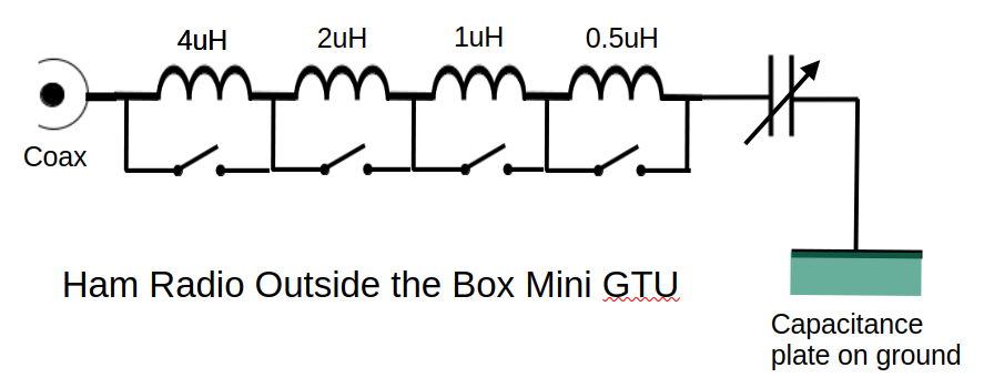
A few weeks Ham Radio Outside the Box published a description of a “Mini Ground Tuning Unit (GTU)”. The schematic for that device is reproduced below. The design was then simplified with input from HROTB-Labs collaborator Tim KQ4TQ. Tim proposed a single inductance with a value of 3 microhenries (and generously donated a prototype he had built).
I built the revised GTU and performed many experiments in HROTB-Labs outdoor test facility (actually, my backyard). Various types of ground planes were tried, from G4AKC’s capacitance plate at the base of his pedestrian mobile radio trolley, to Faraday cloth (“magic carpet”), to ground radials.
My least favorite was the Faraday cloth. The one I used was about 1 square meter in area. I acknowledge the input of Paul VE3PVB who emphasized the need to maximize the area of the Faraday cloth to improve its efficiency. Two things about Faraday cloth are worth noting: first it has a shiny surface which can be distractingly reflective in bright sunshine. Second, it is often referred to as “magic carpet” – a very appropriate term since it has a tendency to fly in even a mild wind. Matt finish paint and a bag of rocks fixes both issues.
I settled on a set of 8 short radials (each 7 feet, or 2 meters long) and they work well. A single long radial wire might be more convenient for rapid deployment in the field. Along with the Ground Tuning Unit (GTU) and a resonant vertical radiating element, a very acceptable SWR is obtained without the use of a tuner.
But back to the GTU and the topic of this TechTip. I tend to rush my projects. Bad! I inadvertently wired my GTU back to front. The result was a significant hand capacitance effect which made precise adjustment of the GTU a little tricky. I had connected the counterpoise (radial wires) to the variable capacitor end of the GTU instead of the inductor end. The result was that, as I adjusted the variable capacitor, my hand was close to the high impedance side of the GTU and became part of the counterpoise.
The fix
I reversed the connections and the situation improved but is not entirely resolved. My GTU layout still brings my hand in close proximity to the terminal where the counterpoise is attached and so the GTU will have to be rebuilt to fix that too. So, if you decide to build your own GTU it would be a good idea to (1) carefully observe the polarity and (2) keep the layout simple to minimize hand capacitance.

Help support HamRadioOutsidetheBox
No “tip-jar”, “buy me a coffee”, Patreon, or Amazon links here. I enjoy my hobby and I enjoy writing about it. If you would like to support this blog please follow/subscribe using the link at the bottom of my home page, or like, comment (links at the bottom of each post), repost or share links to my posts on social media. If you would like to email me directly you will find my email address on my QRZ.com page. Thank you!
The following copyright notice applies to all content on this blog.

This work is licensed under a Creative Commons Attribution-NonCommercial-NoDerivatives 4.0 International License.
Discover more from Ham Radio Outside the Box
Subscribe to get the latest posts sent to your email.
 Ham Radio Outside the Box
Any specification on the variable capacitor? I have always been curious about the approach and would like to build the unit.
Tom
LikeLike
Tom, the value of the variable capacitor is not critical. A polyvaricon with a capacitance around 200pF works for QRP. For QRO a similar value air-spaced variable capacitor is recommended. If the capacitance is too high tuning may become too coarse making the GTU difficult to adjust.
LikeLike