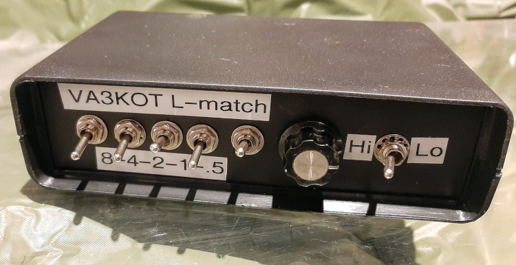
Here is a project that provides a much more efficient way of matching an End-Fed Half Wave antenna than the usual 49:1 impedance transformer. High ratio transformers are prone to inductance leakage, core saturation and overheating leading to low efficiency. Although a 49:1 (or similar high ratio) transformer can present a low SWR to a transceiver, that is not a good indicator of the transformer’s efficiency. It only tells us our radio will not be damaged; it provides no useful information about how much of our signal will actually be radiated. Also, even though a low SWR can be obtained on multiple bands, the radiation pattern breaks up into multiple lobes and nulls on the higher harmonics. End-Fed Half-Wave antennas should really only be used on their fundamental frequency band and its second harmonic.
This L-match can also be used with other high impedance long wire antennas, for example, random wires. With the flick of a switch it can also be used to match low impedance antennas such as verticals.
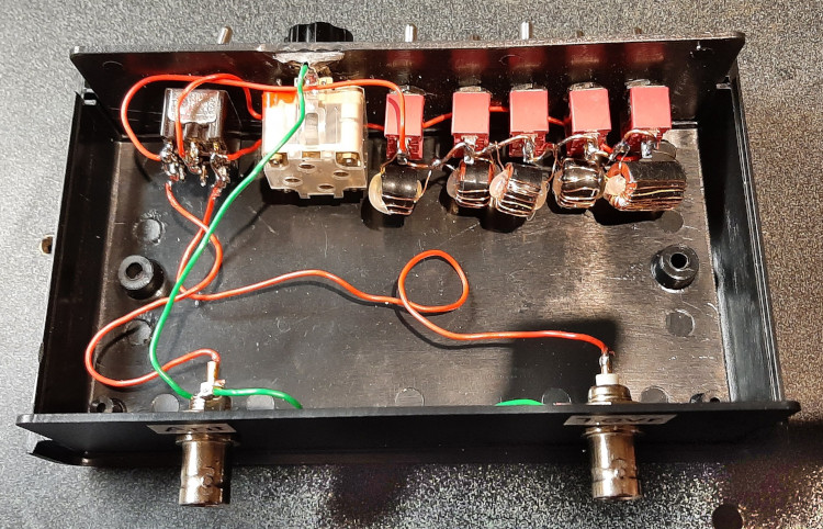
Here is an interior view of the L-match. Note the “expedient” use of T37 toroids since I didn’t have any larger ones. To compensate I used 2 T37-6 toroids for the 0.5uH inductor; 2 T-37-2 toroids for each of the 1.0 – 4.0uH inductors and 4 T37-2 toroids for the 8uH inductor. I have tested the device using 4.5 watts into a dummy load and noted stable SWR with no noticeable core heating. I recommend the use of T50 or T68 toroid cores for anybody wanting to build their own version. The variable capacitor is a 160pF polyvaricon.
There are 10 kinds of people ... those who understand binary notation and those who don’t.
It’s an old joke but it’s quite true. In the binary system there are only two digits to remember: “1” and “0”. We can count from decimal 0 to 31 using only 5 binary digits.

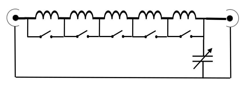
Therefore, with only 5 inductors: 0.5uH, 1.0uH, 2.0uH, 4.0uH and 8.0uH we can select up to 32 values of inductance by binary operation of the switches (NB: “u” in this post represents the Greek letter “mu”, uH referring to microhenries). Inductance values can be selected in increments of only 0.5uH for fairly precise tuning.
A few years ago I built a “Super Tee” QRP tuner that has 7 coils and 7 switches. Additional 0.25uH and 0.125uH inductances were available providing 128 different selectable inductances in increments of 1/8 of a microhenry. My experience has been that it is rarely necessary to use that level of precision in inductance values.
The table below shows how binary selection can vary the inductance between zero (all switches closed) and 31.5 uH in 32 increments of 0.5uH.
| 8uH coil | 4uH coil | 2uH coil | 1uH coil | 0.5uH coil | Total inductance |
| Switch closed | Switch closed | Switch closed | Switch closed | 0.5uH | 0.5uH |
| Switch closed | Switch closed | Switch closed | 1uH | Switch closed | 1uH |
| Switch closed | Switch closed | Switch closed | 1uH | 0.5uH | 1.5uH |
| Switch closed | Switch closed | 2uH | Switch closed | Switch closed | 2uH |
| Switch closed | Switch closed | 2uH | Switch closed | 0.5uH | 2.5uH |
| Switch closed | Switch closed | 2uH | 1uH | Switch closed | 3uH |
| Switch closed | Switch closed | 2uH | 1uH | 0.5uH | 3.5uH |
| Switch closed | 4uH | Switch closed | Switch closed | Switch closed | 4uH |
| Switch closed | 4uH | Switch closed | Switch closed | 0.5uH | 4.5uH |
| Switch closed | 4uH | Switch closed | 1uH | Switch closed | 5uH |
| Switch closed | 4uH | Switch closed | 1uH | 0.5uH | 5.5uH |
| Switch closed | 4uH | 2uH | Switch closed | Switch closed | 6uH |
| Switch closed | 4uH | 2uH | Switch closed | 0.5uH | 6.5uH |
| Switch closed | 4uH | 2uH | 1uH | Switch closed | 7uH |
| Switch closed | 4uH | 2uH | 1uH | 0.5uH | 7.5uH |
| 8uH | Switch closed | Switch closed | Switch closed | Switch closed | 8uH |
| 8uH | Switch closed | Switch closed | Switch closed | 0.5uH | 8.5uH |
| 8uH | Switch closed | Switch closed | 1uH | Switch closed | 9uH |
| 8uh | Switch closed | Switch closed | 1uH | 0.5uH | 9.5uH |
| 8uh | Switch closed | 2uH | Switch closed | Switch closed | 10uH |
| 8uh | Switch closed | 2uH | Switch closed | 0.5uH | 10.5uH |
| 8uh | Switch closed | 2uH | 1uH | Switch closed | 11uH |
| 8uh | Switch closed | 2uH | 1uH | 0.5uH | 11.5uH |
| 8uh | 4uH | Switch closed | Switch closed | Switch closed | 12uH |
| 8uh | 4uH | Switch closed | Switch closed | 0.5uH | 12.5uH |
| 8uh | 4uH | Switch closed | 1uH | Switch closed | 13uH |
| 8uh | 4uH | Switch closed | 1uH | 0.5uH | 13.5uH |
| 8uh | 4uH | 2uH | Switch closed | Switch closed | 14uH |
| 8uh | 4uH | 2uH | Switch closed | 0.5uH | 14.5uH |
| 8uh | 4uH | 2uH | 1uH | Switch closed | 15uH |
| 8uH | 4uH | 2uH | 1uH | 0.5uH | 15.5uH |
If we look at the table below we can see that it would be possible to use even fewer coils and switches if we wanted to operate on fewer bands. For example, if we wanted to operate only on the 20m, 30m and 40m bands we would need only three values of inductance. With five inductances and five switches we can operate on seven bands: 80m, 40m, 30m, 20m, 17m, 15m and 12m. It might be possible to also get a match on the 10m band. The maximum inductance in this project is 15.5uH, but there is additional stray inductance within the internal wiring.
| Frequency (MHz) | Inductance (microhenries) | Capacitance (picofarads) |
| 3.7 | 15.1 | 120 |
| 7.15 | 7.8 | 62 |
| 10.125 | 5.5 | 44 |
| 14.15 | 3.9 | 31 |
| 18.11 | 3.1 | 25 |
| 21.2 | 2.6 | 21 |
| 24.93 | 2.2 | 18 |
| 28.5 | 2.0 | 16 |
Why choose binary selection?
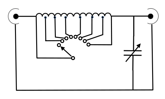
Many designs for L-match devices use a single toroid core inductance with selectable taps as shown in the diagram below. I have built one myself, but as Shakespeare would have said: “Here’s the rub”. It is not easy to build a single inductor with 32 taps at 0.5uH increments. Even if that could be achieved where would we source a 32-way switch? We could use a lead with an alligator clip to select the taps but that would be inconvenient and potentially unreliable out in the field for portable operations.
My own version of this kind of L-match had only 12 taps with a 12-way rotary switch and worked fairly well but was not as versatile as binary selection.
I would like to add my gratitude to Martin K1FQL who provided the math equations and a lot of guidance to me in understanding how L-matches work. I have not included the equations in this post, but if anybody is interested I recommend reading Martin’s post at this link: Highly Efficient L-Matching Networks for End-Fed Half-Wave Antennas.
Coming up on Ham Radio Outside the Box
— Improving the efficiency of an antenna – by burying half of it underground? —

Help support HamRadioOutsidetheBox
No “tip-jar”, “buy me a coffee”, Patreon, or Amazon links here. I enjoy my hobby and I enjoy writing about it. If you would like to support this blog please follow/subscribe using the link at the bottom of my home page, or like, comment (links at the bottom of each post), repost or share links to my posts on social media. If you would like to email me directly you will find my email address on my QRZ.com page. Thank you!
The following copyright notice applies to all content on this blog.

This work is licensed under a Creative Commons Attribution-NonCommercial-NoDerivatives 4.0 International License.
Discover more from Ham Radio Outside the Box
Subscribe to get the latest posts sent to your email.

Just wanted you to know that I love your posts/emails – and that they might just be my favorite thing about ham radio.
I’m new to radio. I started in Nov 2024 with my tech license (US) and got my general in May 2025. I’m not very competitive though, so contesting doesn’t really appeal to me. Listening to folks “rag chew” about medical issues or the size of their boat is only slightly better. I just like the physics of radio, and I like building weird stuff.
While so many operators shuck out thousands of dollars to buy bigger and fancier rigs (and then brag about it), your posts enable and encourage actually understanding the science and then building something neat with it.
Before radio, I was involved in the OTHER hobby involving expensive boxes full of oscillators and filters – musical synthesizers. The DIY spirit is there too, as is the spend-more/ understand-less/ brag-more attitude.
Anyway, many thanks and 73,
Lee KQ4YKN
LikeLike
Thanks for such a great comment Lee. Experimenting with radio technology is one of the reasons we are given free access to large parts of the electromagnetic spectrum. Many hams, like you and I, find that aspect more satisfying than simply using radio as a chat medium. The physics of radio is fascinating, especially when we consider ideas like what the Inverse Square Law does to our signals. I recently read about the received signal strength from the Voyager 1 spacecraft which has left the Solar System. It gives new meaning to “QRP”. The fact that we can still send and receive data to and from Voyager despite the vast distance and long signal delays involved makes our ham radio experiments seem insignificant. I enjoy experimenting on a much smaller scale. Some experiments work while others are “a learning experience”, that’s all part of the fun.
LikeLike
I built a similar one based on this post: https://wb3gck.com/2021/06/21/inside-my-old-tuner/ and I find that it matches almost anything. I added a built-in CMC, a tuning indicator and a magnetic attachment point for a counterpoise. When the weather improves (enough for my family to be willing to go to a park) I plan to try it with a CB antenna and a 13′ counterpoise.
LikeLiked by 1 person
I’ve enjoyed several of your articles and this one is close to something I’m gathering parts for for my QRP-Labs QMX+.
A couple of things aren’t clear to me:
Do you still use an impedance transformer with this? From Martin K1FQL’s post it looks like no.
How is the Low / High switch wired?
John, W5JSS
LikeLike
Thanks for getting in touch John. No impedance transformer is needed. In fact the L-match itself is an impedance transformer. The high/low switch changes the connection of the variable capacitor. In the high position the variable capacitor is connected to the output (antenna). In the low position the variable capacitor is connected to the input (transceiver). The switch can be eliminated and the high/low impedance can be selected by simply reversing the coax connections.
LikeLike