Is it Standing Wave Ratio (SWR)?
It is common knowledge that when an antenna has high SWR some of our transmitted power is wasted instead of being transmitted. But is this really true? The trouble with “common knowledge” is that it spreads without further scrutiny. “It must be true because that’s what everybody thinks”. But let’s consider another perspective.
What happens to our signal when it meets an antenna with high SWR? Some of the signal is radiated while the rest is reflected back down the transmission line to its source – the transceiver. What happens to the reflected signal when it reaches the transceiver? It is re-reflected back towards the antenna and the cycle repeats.
So does all the signal eventually get radiated? No. Energy is lost (RED ALERT from the physics department: Energy can neither be created nor destroyed, only converted from one form to another). Ok, my apologies to the physics department, some of the energy is converted to heat as our signal passes along the transmission line and through any ununs, baluns, impedance transformers or other devices en route. Further energy is converted to heat due to the resistance of the wires and the impedance of the transmission line itself.
Thus, on every trip between the transceiver and the antenna, some of our transmitted RF is converted to heat. If the antenna has a high SWR some of our signal travels back and forth between the transceiver and the antenna multiple times and becomes further attenuated on each trip. Therefore, if we can reduce the loss of RF (due to conversion to heat) as it passes through any devices along the journey between the source (transceiver) and load (antenna) we will improve the efficiency of our antenna system.
How can we do that?
One simple way to achieve that is to correct for the high SWR right at the antenna. A remote tuner can do that. A loading coil will compensate for the high capacitive reactance of a short antenna, but loading coils can be inefficient because of wire resistance. This is especially true in the case of base-loading coils on a quarter-wave vertical antenna. The current is highest at the base of the antenna so more RF energy will be lost to heat (P=I^2*R) than with a center-loading or top-loading coil.
So the real culprit is not SWR, but the insertion loss of ununs, baluns, impedance transformers, loading coils, transmatches and any other “energy conversion” devices, including the transmission line itself, through which our signal has to pass.
Insertion loss of Ham Radio Outside the Box’s 4:1 ununs
In the previous post I reported on my build of field test versions of a 4:1 unun and a 4:1 balun to compare how each would handle the task assigned to them. Now the job I set myself was to transform what might be called the “Ugly Sisters” builds into something with the good looks of Cinderella. And Cinderella had to be an unun tough enough to withstand rough treatment out in the Big Blue Sky Shack through all four Canadian seasons (Late Winter, Brief Summer, Early Winter, Deep Winter).
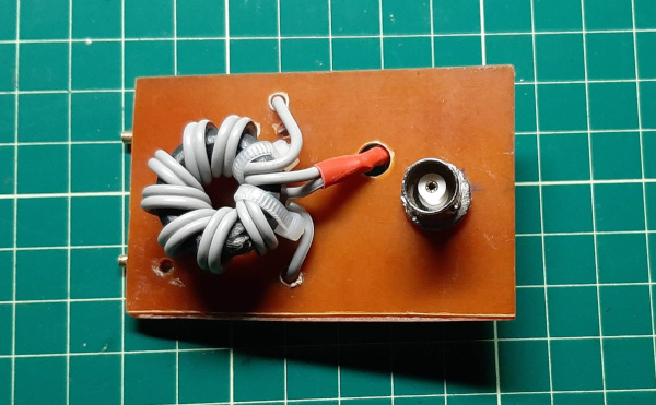
I built two versions of a 4:1 unun; one for QRP and another for what I like to call QROp. “QROp” is an unofficial label I have adopted to mean about 20 watts or so. Twenty watts will give a 1 S-unit advantage over 5 watts – maybe just enough for our signal to poke its nose above the noise floor when propagation conditions are not so good.
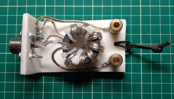
There are 2 main differences between the QRP and the QROp versions: The QRP unun uses a BNC connector and a 4:1 transformer wound on a tiny FT82-43 toroid. The QROp version uses an SO-239 connector and a 4:1 transformer wound on an FT140-43 toroid.
If we look at the tables below, we can see that the QRP version may have a little too much insertion loss. When we are trying to do as much as we can with as little as possible every milliwatt is wanted. As the wonderful friendly folks on the big Canadian island of Newfoundland like to say: “A little’s a lot if it’s all you’ve got”.
Insertion Loss effects of the Ham Radio Outside the Box QRP unun
| Band | QRP (5 watts) UNUN Insertion Loss (dB) | RF Power Lost (watts) | % RF Power Lost |
|---|---|---|---|
| 10m | 0.39 | 0.43 | 8.6 |
| 12m | 0.37 | 0.41 | 8.2 |
| 15m | 0.35 | 0.39 | 7.8 |
| 17m | 0.34 | 0.38 | 7.6 |
| 20m | 0.33 | 0.37 | 7.4 |
| 30m | 0.32 | 0.36 | 7.2 |
| 40m | 0.35 | 0.39 | 7.8 |
| 80m | 0.73 | 0.77 | 15.4 |
Insertion Loss effects of the Ham Radio Outside the Box QROp unun
| Band | QROp (20 watts) UNUN Insertion Loss (dB) | RF Power Lost (watts) | % RF Power Lost |
|---|---|---|---|
| 10m | 0.24 | 1.08 | 5.40 |
| 12m | 0.23 | 1.03 | 5.15 |
| 15m | 0.22 | 0.99 | 4.95 |
| 17m | 0.21 | 0.94 | 4.70 |
| 20m | 0.20 | 0.90 | 4.50 |
| 30m | 0.20 | 0.90 | 4.50 |
| 40m | 0.20 | 0.90 | 4.50 |
| 80m | 0.22 | 0.99 | 4.95 |
A little extra heat in winter
You would think Canadians wouldn’t mind a little extra heat in winter. It’s true, but not when the source of that heat is our precious transmitted RF. In case you were wondering, the amount of RF converted to heat by inefficient devices is mostly undetectable. If it can be easily detected the “magic smoke” can’t be far behind. When it’s 253 Kelvins outside you just ain’t gonna notice when the temperature rises to 254 Kelvins (note: the physics department advised me to use Kelvins to avoid confusion between degrees Fahrenheit and degrees Celsius).
Oh no! There’s more?
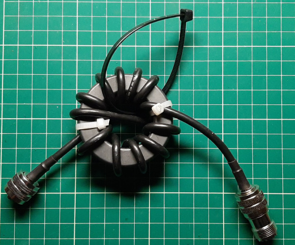
Yes indeed. An unun does not attenuate Common Mode Current (CMC). For that we need a Common Mode Current Choke (CMCC). CMC is the current on the outer surface of a coax braid. Differential mode current is carried on the core and inner surface of the coax braid. Does a CMCC also have insertion loss? Yes, but how much? Let’s take a look.
Insertion Loss of a QRP (5 watts) Common Mode Current Choke (CMCC)
| Band | QRP (5 watts) CMCC Insertion Loss (dB) | RF Power Lost (watts) | % RF Power Lost |
|---|---|---|---|
| 10m | 0.25 | 0.28 | 5.6 |
| 12m | 0.22 | 0.25 | 5.0 |
| 15m | 0.21 | 0.24 | 4.8 |
| 17m | 0.19 | 0.21 | 4.2 |
| 20m | 0.17 | 0.19 | 3.8 |
| 30m | 0.15 | 0.17 | 3.4 |
| 40m | 0.14 | 0.16 | 3.2 |
| 80m | 0.13 | 0.15 | 3.0 |

Insertion Loss of a QROp (20 watts) Common Mode Current Choke (CMCC)
| Band | QRP (5 watts) CMCC Insertion Loss (dB) | RF Power Lost (watts) | % RF Power Lost |
|---|---|---|---|
| 10m | 0.18 | 0.81 | 4.05 |
| 12m | 0.16 | 0.72 | 3.60 |
| 15m | 0.15 | 0.68 | 3.40 |
| 17m | 0.13 | 0.59 | 2.95 |
| 14m | 0.11 | 0.50 | 2.50 |
| 30m | 0.10 | 0.46 | 2.30 |
| 40m | 0.09 | 0.41 | 2.05 |
| 80m | 0.08 | 0.37 | 1.85 |
The (not so) grand total of RF going up the chimney
| Band | Total QRP (5W) % RF power lost to heat | Total QROp (20W) % RF power lost to heat |
|---|---|---|
| 10m | 14.2 | 9.09 |
| 12m | 13.2 | 8.75 |
| 15m | 12.6 | 8.35 |
| 17m | 11.8 | 7.65 |
| 20m | 11.2 | 7.00 |
| 30m | 10.6 | 6.80 |
| 40m | 10.0 | 6.55 |
| 80m | 18.4 | 6.80 |
The white bearded man in the red suit and his flying reindeer might be grateful for a few watts of heat going up the chimney at this time of year, but those of us in the frozen barren tundra of the northern states and provinces, as well as licensed ham dwellers in other cold lands, may not see things the same way.
What can we conclude?
If we only consider the insertion loss – in this example – of the 4:1 voltage unun and the Common Mode Current Choke and ignore resistive losses in the transmission line, and possibly insertion loss in a transmatch (“tuner”), we can determine the potential efficiency of our antenna system.
- For our QRP devices the efficiency varies between 81.6% and 90% across the bands
- For our QRO devices the efficiency varies between 90.9% and 93.5% across the bands
This conclusion is based on the assumption that there is no loss in the antenna itself. We are treating the antenna, the transmission line, unun and CMCC as the “antenna system”. I have made no allowance for SWR losses for the reasons stated in the introduction to this post.
What a load of old codswallop!
I am an expert in the sense that “X” is an unknown quantity and “spurt” is a drip under pressure. I may be completely wrong; I may have fallen off my horse and bumped my head on a rock. I may have come to a fork in the road and taken it as Yogi Berra once famously said. If you would like to correct me on any wrong assumptions please do so. I receive a lot of direct emails from readers and, while they are most welcome, if you write a comment to this post instead it may trigger an interesting technical discussion here.
A big thank you to all the new and many existing subscribers to Ham Radio Outside the Box. It is people like you who make writing these posts so worthwhile. I appreciate every one of you.

Help support HamRadioOutsidetheBox
No “tip-jar”, “buy me a coffee”, Patreon, or Amazon links here. I enjoy my hobby and I enjoy writing about it. If you would like to support this blog please follow/subscribe using the link at the bottom of my home page, or like, comment (links at the bottom of each post), repost or share links to my posts on social media. If you would like to email me directly you will find my email address on my QRZ.com page. Thank you!
The following copyright notice applies to all content on this blog.

This work is licensed under a Creative Commons Attribution-NonCommercial-NoDerivatives 4.0 International License.
Discover more from Ham Radio Outside the Box
Subscribe to get the latest posts sent to your email.

Consider that SWR is really a property of a transmission line and not so much the antenna itself. Antennas are impedance transformers with an input (feed point) impedance and output impedance which couples to free space.
An mismatch between the transmission line (TL) characteristic impedance and feed point impedance causes energy to be reflected to the TL where it constructively and destructively interferes with the incoming signal, giving rise to standing waves.
None of this is an argument against your discussion of power lost as heat in the TL system instead of being efficiently coupled to the aether. Rather, it’s just looking at the terms with higher fidelity, perhaps. And no doubt, there will be physicists and engineers to set me straight 😉
LikeLike
Quite right Matt. The Standing Waves are on the transmission line and are caused by the mismatched antenna. Thanks for the input.
John Corby, VA3KOT HamRadioOutsideTheBox.ca
LikeLike
No arguments at all with your theory and explanations John. They mesh very well with other explanations.
Yet, being a fastidious nit-picker, it might be better to replace “14m” in the first column of all charts with “20m.” …or, change all the rest to appropriate Mhz.
No matter however: to survive 3 variations of winter, what’s wrong with a little heat.
Best de N4REE, Bob
LikeLike
Thanks Bob, my careless mistake.
John Corby, VA3KOT HamRadioOutsideTheBox.ca
LikeLike
Hello John VA3KOT, I’m studying for my HAM license… slowly; Not quite as slow as molasses in Winter, but close. VA3 zone here too. I’m learning all I can re QRP and what you call QROP too, as that will likely be my favoured HAM activities. I’m thinking that low power ops raises the bar for efficiency and good antennas, plus learning / playing at understanding their proper use. Thus, I appreciate you sharing your experience and experimental results. Thank you.When I see pictures of QRP-QROP ununs, baluns and CMCCs, I take notes. I count. Am I wrong to say that in your QROp CMCC image, there’s 6 or 7 turns on the top but only 5 or 6 on the bottom? I don’t know how one counts or ignores the cross-over pass. It would seem to count as one for both sides, or a half for each. Is the inequality I perceive intentional? Am I seeing it right?——— Re the lower efficiencies at the 80 and 10 meter ends, is that because we are nearing the limits of the 43 material? Would other ferrite materials be better or worth experimenting with for the lower or upper ends?
Kind thanks,
Marc P
in ON, where winter is coming, correction – has arrived again!(Cool reply text box functions!)
LikeLike
Hi Marc, thanks for your comment and good luck with your ham license study. Ham radio is a very rewarding hobby that I am sure you will enjoy a lot. Regarding the QROp CMCC, every time the coax passes through the core counts as one turn and that includes the crossover turn. The crossover turn simply allows the ends of the coax to come out on different sides of the core. I believe the issue with 80m on the QRP unun may be due to lack of inductance on such a small core. I rarely use 80m when operating portable so it’s not a problem for me.
LikeLike
Thank you, John. I appreciate it.
LikeLike
John –
Superb article – Thank You. Only one comment: When the reflected power gets back to the transmitter, all of it MAY NOT be re-reflected. Depending on the transmitter output design, the reflected power may may actually damage the transmitter final amplifier stage.
A properly adjusted ‘Antenna Tuner’ solves this by providing an impedance (toward the antenna) that DOES re-reflected this power back to antenna, where most is radiated. At the same time, the tuner also provides an impedance toward the Transmitter that is nearly 1:1. The tuner doesn’t ‘tune’ the antenna, just the radio output impedance.
Particularly with experimental antennas, always use a tuner (or low power) with the radio until the antenna is properly tuned.
Again – you are a GREAT source of RF truth, which is NOT easily acquired. And no, I don’t sell Tuners!
– A Colorado Friend.
LikeLike
Thanks for your kind words and value-added detail!
LikeLike