What is the best way to match the very high impedance of an End-Fed Half-Wave antenna to the 50 ohm impedance of a transceiver? There are various ways to do this but this week’s post is going to focus on just two – a 49:1 impedance transformer (or UNUN if you prefer) and an L-network.
We are dealing with QRP devices but the same issues arise with QRO devices. In fact some of the complexities may be exacerbated at higher power – especially core overheating.
49:1 impedance transformer
This is by far the most widely used matching device but many claim it is inefficient. I have used an “Outside the Box” winding method that I have seen described as “Fuchs style”. The primary and secondary windings are entirely separate instead of being twisted together. This method isolates the windings and is said to prevent static from traveling back down the coax to damage the transceiver. But it also requires a separate 0.05WL counterpoise connected to the bottom of the secondary winding.
Pros
- Broadband operation
- Easy to construct
- No calculations needed
Cons
- Lower efficiency claimed
- Can be used on even harmonics but the antenna is only a half-wave on its fundamental frequency
- Potential for losses due to core overheating
- Leakage flux due to poor coupling between windings
- May require capacitance across primary and/or secondary to compensate
L-network

Some claim that an L-network is more efficient than an impedance transformer. While I don’t dispute the claim I would respond “show me the math”. An L-network is usually constructed from a fixed value serial inductor and a fixed value parallel capacitor (although there are other topologies depending on the matching parameters involved). I built one using a slug-tuned variable inductor and a ceramic trimmer capacitor.
Pros
- Higher efficiency claimed
- Easy to construct
- Avoids complex issues with transformer cores and winding coupling
Cons
- Single band only
- Calculations required to establish correct values of L and C
The Ham Radio Outside the Box laboratory (a grand name for my basement workbench) has built many 49:1 impedance transformers for both QRP and QRO operation. The QRP units are deployed in backpack portable operations and the QRO units have seen service both in the field and in the home shack. Both the conventional “twisted” coupling method and separate windings have been used.
Which winding method is best?
One of the issues with 49:1 transformers is “leakage flux” which means not all of the energy in the primary winding is coupled to the secondary. The conventional winding method is to twist the first two turns of the primary and secondary together to improve coupling. The remaining turns are only coupled to the primary by the flux in the core. Furthermore, there is often a “crossover” turn to bring the far end of the secondary out on the opposite side of the core from the primary. This may further reduce the coupling efficiency.
An alternative method is to wind the secondary, without a crossover turn, around the core. The separate primary is then wound around the center of the secondary. Should the secondary be spread around the core, or closely spaced? Opinions vary on this. I now favor keeping the secondary turns closely spaced. The reason? A closely spaced secondary winding should improve inter-winding coupling and reduce leakage flux.
What about the turns ratio?
Should it be 49:1, 64:1 or …? There is an easy answer to that: just divide your antenna impedance by 50 and bingo, there’s your answer. Oh, but what is the impedance of your antenna, 2000 ohms, 2319.647 ohms, 3000 ohms? We don’t actually know and it may vary depending on how the antenna wire is erected (which for portable operators may be different every time). A ratio of 49:1 provides a good enough match to most every value of End-Fed Half-Wave (and multiples) we are likely to experience.
Or just build an L-network!
We have seen that 49:1 impedance transformers have many variables that impact efficiency. Leakage flux has been discussed so it is relevant to note that placing a small capacitor (typically 100pF) across the primary winding is recommended to somehow compensate. Conventional 49:1 transformers are wound as autotransformers, so we have a series inductor between the antenna and the radio, and a parallel capacitor. Doesn’t that sound very similar to one of the topologies of an L-network?
My initial experiments with building L-networks involved a fixed series coil and a parallel capacitance made from a short length of thin coax – like RG-174. I experienced the problem that the calculated values of L and C did not provide the best possible match to 50 ohms. I still needed a “touch-up” tuner to bring the SWR down to a safe level for my QRP Labs QMX transceiver. I realized that a field portable antenna was going to need slightly different component values depending on whether my temporary station was setup on exposed ancient bedrock, or over the moist ground at the edge of one of the Great Lakes. What I needed was an L-match “tuner”, i.e. an L-network with variable inductors and capacitors.
42 years ago …
A long, long time ago (42 years to be precise) I was a penniless SWL foraging for food in the forest – alright that’s an exaggeration, but I had a young family and couldn’t spare the cash to buy a decent shortwave receiver. A friend told me about a design in Practical Wireless magazine for a shortwave converter that would work with a regular domestic AM receiver. I had the components shipped over from the recommended UK suppliers and built the converter. It worked splendidly and I spent many happy hours listening to the busy shortwave bands. Then I became fabulously wealthy (i.e. I could at last afford shoes and to eat every day of the week), bought a real HF radio and the converter was relegated to the back of a closet.
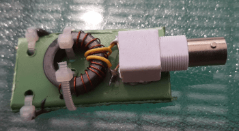
The point of the story is that I was able to scavenge that converter for the components I needed to build an L-match for an End-Fed Half-Wave antenna. The inductor shown in the picture above is wound over an adjustable slug-type ferrite core of unknown mix. The capacitor is a ceramic trimmer with a couple of fixed ceramic capacitors in parallel to bring its value into the range that was needed. The only comment I can make on the efficiency of that unknown core is that it didn’t get hot (or even warm) after an extended period of transmitting at 5 watts. Tuning is quite sharp but I was able to get a 1.5:1 SWR from my Shortened Sloping End-Fed Half-Wave antenna (see last week’s post). I probably could have obtained an even lower SWR by adjusting the length of the high Q top section of the SSEFHW.
QSO’s?
As a recent convert to L-networks I have only made enough QSOs to be countable on fingers and toes. On the other hand, over the years, I have made thousands of QSOs with a 49:1 impedance transformer. Both the devices shown in the pictures above accompany me on every field portable outing so I have options and can compare their performance.
Does it matter, really?
Sometimes I give my head a shake and tell myself to put the physics textbooks back on the shelf and just enjoy the experience of being out in the Big Blue Sky Shack with my radio. At other times, after calling CQ ’til the cows come home and getting no responses, I ponder the question of whether my antenna is doing its job or, as sailors used to say, is idly “swinging the lead”.
What are your experiences with either impedance transformers/UNUNs or L-networks? Your opinions are very welcome either by adding a comment below, or if you prefer, by email (QRZ.com).

Help support HamRadioOutsidetheBox
No “tip-jar”, “buy me a coffee”, Patreon, or Amazon links here. I enjoy my hobby and I enjoy writing about it. If you would like to support this blog please follow/subscribe using the link at the bottom of my home page, or like, comment (links at the bottom of each post), repost or share links to my posts on social media. If you would like to email me directly you will find my email address on my QRZ.com page. Thank you!
The following copyright notice applies to all content on this blog.

This work is licensed under a Creative Commons Attribution-NonCommercial-NoDerivatives 4.0 International License.
Discover more from Ham Radio Outside the Box
Subscribe to get the latest posts sent to your email.

I use EFHWs almost exclusively. I have three set up at home and have various others I drag along on outdoor operations. I have 1000s of DX contacts @ 100W and many hundreds of European, S., and central American QSOs at 10W or 5W, mostly SSB.
The TennTenna “40 m” un-un with around 64 feet of wire is usable on 2m through 40m without a tuner. It also tunes on 80 and 160 (with difficulty) on my IC-705 and MAT tuner.
My EFHW antennas out-perform any vertical I’ve tried by 1-2 S units, and any of the two mag-loops I’ve owned by 2-3 S units. I’ve made contacts with just 32 feet of wire lying on a wooden bannister, 3.5 feet up, at a beach.
If it wasn’t for the “vendor community” that supports much of this hobby and which survives by selling 32′ of wire and a coil for $189.95, there would be no controversy or question at all of which antenna provides the best performance for the lowest price and effort, i.e. VALUE.
It is an EFHW, 64 feet, 49:1, HANDS DOWN.
I’m eager to see the math on efficiency for a 49:1 vs. L-network. My guess is one is not more than around 20% better or worse than the other. Not like the huge difference between EFHWs and loops. IOW, it makes no practical difference.
LikeLike
Thanks for the feedback! I don’t understand why EFHWs get so much bad rap. I have been using them too for many years with great success. Verticals may be good for DX but not so good for closer QSOs. Mag loops seem to work too but their very high Q makes them a pain to retune if you QSY a lot.
LikeLike
If radio is like any other human endeavor the bad rap probably originated with one or more vendors with something (other than EFHWs) to sell. Then highly experienced “thought leaders” (Internet Radio Ninjas) pick up the vibe and promulgate it. People looking for acceptance as part of the hobby’s influencers, parrot their B.S. One of the most experienced hams at a local club once referred to EFHWs as “dummy loads.”
My only antenna for my first 5 years was a 32 foot EFHW strung up in my attic. I purchased a fan dipole for outdoors and never got it up because everything tangled. After 3 hours of frustration I wound up throwing the damn thing in a box and shipping it back to the supplier (I did not get a refund 🙂 )
If you ever need a hard break from feeling good and happy may I suggest a mag-loop POTA activation on a day with poor propagation? I made a total of two contacts but no complete QSOs. I lost both when I got up to turn the thing in the direction of my caller, and when I returned to the radio both ops were gone.
LikeLiked by 1 person
If I ever have the time I’m going to do an experiment, a 32′ EFHW + 49:1 vs. my mag loop. Most of us know what the result will be.
The EFHW will out-perform the loop, even when the loop is turned to the direction of my contact. It will out-perform the loop while lying across a picnic table into a bush, no more than 5-6 feet high.
But, btw, thanks for a thought-provoking article. I’m looking for a QRP L-match as I type this!
LikeLike
MFJ made an L-match (16010) but its a 200 watt model and may be hard to find now MFJ has ceased production. If you are into DIY you could make a QRP version for just a few bucks.
LikeLike
Like you, John, I became wealthy a long time ago Yet, I scratch build nearly every antenna (except, not good at making telescopic metal tubing yet), and have a huge pile of rejects to prove the point. [NOT one to spend $189 for 32′ of wire! … Scotch heritage!]
My ~66′ EFHW inverted vee, supported at the mid-point by a too frequently collapsing plastic telescopic mast sees daily duty. My traditionally wound 49:1 transformer uses a Fair-Rite 2643625002 core (per MM0OPX) and a 100pF cap. The transformer is right at the base of the wire, and is followed immediately by a common choke and the coax (length irrelevant).
I use it everyday as my preferred antenna for 40m, 20m, 25m, 10m with no tuner and all of my QRP rigs are happy using it with no tuner. It is deployed her in my neighbor friendly HOA over very poor Florida soil (the charts in the ARRL Antenna book show “yuck!” for this soil).
Yesterday, I did a “shoot out” between this EFHW and a 20m setup of the raised radials PERFormer vertical. While I like the PERFormer, it is a single-band-at-a-time antenna that isn’t as quick to adjust as the inventor claims. The EFHW measured about 30% better in number of WSPR spots and the SNR values of those spots. I’m sticking with it as my baes / reference antenna.
No, I haven’t tried an L network, and likely won’t because I dislike fudding with fiddly little screw-like things.
As always, thanks for your ideas, and new ways of building more DIY antennas.
LikeLike
Thanks Bob. L-networks can be as simple as a fixed coil with a few inches of coax acting as a capacitor, but they are single band. For multi bands an L-match tuner is needed. The 49:1 unun makes life so much simpler at (maybe) the expense of a little efficiency. BTW, I love Florida, been there many times but not so keen on all the snakes and gators!
LikeLike
What was that thumping we heard in the garage last night? Remotely opened the door until it went away.
LikeLiked by 1 person
I liked the comments. EFHW does work well. Ease of setup means I can use it more often.
I’ve done a lot of testing over the years with 49:1 and 64:1 UnUns — using a VNA in back to back, and also in resistive termination method. I’ve compared the efficiency results to testing with key-down power into a fully installed antenna over time, then calculating loss using temperature rise measurements. The results differed by only a few percent. The worst of the ones I built was around 40% loss and the best around 5% loss. Loss in EFHW antennas due to UnUns and claims of saturation is not a consideration. At the powers we use portable, and 100W, saturation is not an issue. Same for harmonic distortion. Heating with high efficiency design is similarly not an issue. I now only use them with an integrated 1:1 balun and mandatory radials because of the 1:1. I measure common mode current with a clamp on meter at the transceiver – the 1:1 sees a reduction of about 10:1 which is sufficient to prevent problems for me.
For me, the ability to get up on air quickly makes the EFHW a winner. Modelling indicates a 6m extending fishing pole with an EFHW setup as an efhw and 20m (63ft approx) of wire has low angle for DX on 20m, and mostly NVIS for 40m local/interstate contacts. It is the best of both worlds.
LikeLike
Thanks for the feedback Richard. Based on your testing I guess any inefficiency in the UNUN must be down to how well the windings are coupled. I started out with the popular winding style of twisting the primary with the first 2 turns of the secondary with a crossover turn on the secondary. Lately I have been trying separate windings (primary 2t wound over the center of the 14t secondary) and connecting a counterpoise to one end of the secondary with the 63ft wire at the other end. I will try both methods terminated in a resistor and attempt to measure the comparative power transferred to the load.
LikeLike
Hi John, thanks kindly. I think efficiency is a multi-headed monster. The 2 turn primary is required to match to 50R for a huge bandwidth. At 80m vs 10m there is a vast difference in the load it presents to the radio. I have been using 3 turn primaries – at 160m to 20m it has far less loss maybe less than 0.1dB depending on the core(s), but at 10m it usually craters significantly, 3dB loss or more. Here in VK 10m is not busy and I work 80 to 20m exclusively so that suits me.
My understanding on loss is that there are many factors and core geometry and of course type are critical. I use the autotransformer approach. I could expand on all that, but my experience is that 2 stacked cores usually brings better efficiency, often at the expense of loss in 10m band, maybe 15m as well. Getting 95% and more efficiency in the lower bands suits me. Losing 1/2 an S point on a band I use once a year at most is not an issue.
I tried the isolated primary wound over the top of the secondary. That gave me more efficiency, but the common mode current was highest and difficult to suppress. It surprised me. Common mode current in the coax laying on the ground feels like lost signal. If you have the time etc, do build a common mode meter, or buy one etc. They are worthwhile for discovering some of the hidden things many overlook.
I never pursued the isolated primary (it still feels like a good idea). I am thinking that I’d like to try winding the isolated primary over the “earthy” radial end of the secondary. FWIW I enclosed the primary in teflon tube.
One final (contentious) comment is that I use 2 radials, both same length of 1/20th wavelength of the longest band. I found that gave me a better SWR – note – I use a 1:1 in the same box as the UnUn, and I use a 64:1 UnUn – I found that 64:1 gave a little better SWR when using the 1:1. I may well be wrong – but those were my observations.
Kind regards Richard, VK3TXD
LikeLike
Every antenna is a compromise in some way. A balance of efficiency, ease of use and portability.
I use the EFHW when portable, but wind the antenna length out to the proper length for the band I’m on. A little effort and knowledge can save a lot of weight.
At home, I use a 35′ longwire with a 17′ counterpoise, because it all has to fit inside my apartment. There, I use an L match tuner to work 40 to 12 meters. Too much noise on 80 and the 10m band doesnt work on my old HW-9.
Use what’s simple and practical for YOU. A few db or other people’s opinions don’t really matter.
LikeLiked by 1 person
I like the idea of winding out the correct wire length to match the band in use. I use a linked EFHW for 20m, 30m and 40m myself. Similar idea. Thanks for commenting Rick.
LikeLike
A fine read! I too, enjoy the experimental aspect of this hobby, but only after going down every rabbit hole found along the way. I’ve only begun four years ago and already wish I had started sooner, as I’m afraid that I will run out of “time” before I get to do all that it has to offer. 😉 73 DE KN6UIZ
LikeLike
Thanks for the comment Jason. Yes none of us are getting any younger. I don’t like to tell people my age when on the radio because it always ends the QSO – I am 73! Life just ain’t long enough to learn all there is to know about ham radio, that’s for sure.
LikeLike