I have been reading a lot from the “Ban all End-Feds” brigade lately. The animosity towards feeding a wire antenna at one of its ends approaches supernova intensity at times. Some of the opinions expressed are perfectly valid, true and backed up with sound science and math. But some of the denizens of end-fed doom have dug in, set up a perimeter and defend their position at all costs.
Let’s take a step back for a moment and consider this idea: Aren’t all antennas fed at the end of something? Could be a wire, could be a transmission line. There are lots of strongly held beliefs about transmission lines too. Coax bad, Open Wire Line (OWL) good. Sure OWL transmission lines are significantly less lossy than coax – in certain circumstances. Open Wire Line is often replaced with window line which behaves differently when it gets wet. And coax; what type, how long?
RG-58 has a loss of about 1.5 dB per hundred feet on HF. If you run 200 feet of the stuff you will lose half your power. I use 25 feet of RG-58 for some of my backpack portable ops, that’s a loss of 3/8 of a dB.
What’s better than very low loss Open Wire Line or coax? No transmission line at all! In certain circumstances an antenna can be directly connected to a radio. That works well out in the Big Blue Sky Shack and with low power. If you are a QRO op and you do that you may experience a comfy warm feeling, especially between the ears.
But let’s get back to end-fed antennas. They come in two main varieties: End-Fed Random Wires (EFRW) and End-Fed Half-Waves (EFHW). It is very inadvisable to erect a random wire! Oh? Why is that? Because only certain lengths will work. If your random wire turns out to be close to a half-wavelength long on any band you wish to work, it will not “load”. The impedance at the end of any antenna wire varies greatly depending on frequency and length of the wire.
So, no problem; just use a 9:1 unun and it will bring the impedance down to a level that the “Magic Button” (Tune) on your radio can handle? Ham Radio Outside the Box has covered that fallacy already. A 9:1 unun will transform a resistive impedance of 450 ohms down to a perfect 50 ohms. But what if the impedance of the EFRW is much less than 450 ohms?
That “Magic Button” can take of that situation too, can’t it?
“Press the Magic Button
And soon you’ll see
Your antenna is so perfect
In the land of fantasy”
- Sincere apologies to Peter, Paul and Mary
The radio’s tuner keeps the transmitter happy but the antenna is unchanged. It’s like wearing contact lenses; you can see perfectly, but your eyes are still bad.
An EFRW antenna can be tuned on multiple bands and a 9:1 unun can’t be guaranteed to deliver an impedance that a tuner can handle in any situation. You might get lucky or you might find some bands can’t be tuned. As somebody in the Ban End-Feds Brigade once said: “impedances will be all over the Smith chart, so leave out the 9:1 unun and let the tuner do its job.”
Fire and Brimstone
The brigade has a particular dislike for the End-Fed Half-Wave antenna, but their proverbial fireballs of burning sulfur are directed principally toward vendors of commercial EFHWs who package up a 49:1 unun with some wire and claim their antenna requires no tuner on the design frequency and it’s harmonics (e.g. 40m, 20, 15m, 10m). In reality an EFHW is only actually a half-wave on one specific frequency. Ham Radio Outside the Box has discussed this issue before so we won’t go over it again here. Instead let’s focus on the 49:1 unun (aka impedance transformer).
The Universal UNUN
What is the impedance at the end of a half-wave wire? First, let’s make it simple and satisfy one of the objections of the brigade; let’s make it a monoband antenna. Is the end impedance exactly 2450 ohms (50 ohms times 49 equals 2450 ohms)? If it isn’t, does it matter? I decided to find out.
Revisiting the CLEFHW
My Coil-Loaded End-Fed Half-Wave (CLEFHW) has been a stirling performer so far. To recap, it comprises an 18.5ft vertical telescoping whip with a base loading coil that makes it an electrical half-wave on the 20m band. But the SWR has always been a little outside my comfort zone – usually around 1.8-1.9:1. That’s not an unreasonable SWR but my current favorite radio (QRP Labs QMX) has a reputation for blowing its SWR fuses (aka PA transistors) if it encounters standing waves it doesn’t like.
I wondered if the CLEFHW’s unorthodox design caused the feed point impedance to stray from a nominal 2500 ohms, so I set up a test arrangement on the bench using a ham brew 2500 ohm dummy load to investigate.
The Dummy Load
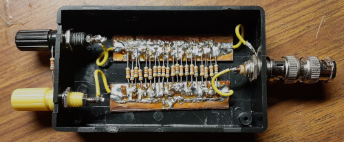
I only had 1/4 watt resistors in my shack – hundreds and hundreds of them, but I needed a dummy load that could withstand a QRP “full gallon” (5 watts) of power. I jotted my thoughts down using my favorite text editor “Joplin”. You can follow the logic of my thoughts from the screen print of the Joplin file below.

I built the dummy load using 10x47K and 10x56K resistors all in parallel. The resistors have a tolerance of 10% and the final product measured 2500 ohms. Note the binding posts on the left in the picture above. These allow extra resistors to be added. For example, adding 6800 ohm in parallel with the 2500 ohm dummy load yields 1800 ohms. This allows me to experiment with various dummy load resistances.
It was necessary to make a big assumption when using the dummy load – that any antenna I might be using would be purely resistive with no capacitive or inductive reactance. Then, to check out the “Universal Unun” with a 49:1 impedance ratio, I simply used my antenna analyzer to measure the SWR while I adjusted the turns ratio.
The results are tabulated below:
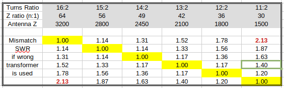
As can be seen, a 49:1 impedance transformer works fairly well in transforming various antenna impedances down to near 50 ohms. In fact, it is almost as good as a 42:1 transformer which will give 1.5:1 or less over a wide range 1500-3200 ohms) of antenna impedances.
Using this method I established that my CLEFHW antenna has a feedpoint impedance of 1800 ohms. I adjusted the turns ratio of my QRP unun to 36:1 and the real world (snow covered driveway) SWR dropped from 1.8-1.9:1 down to less than 1.5:1. If this winter ever ends and the glaciers retreat from the local parks, the new improved CLEFHW will be getting a good workout this summer.

Help support HamRadioOutsidetheBox
No “tip-jar”, “buy me a coffee”, Patreon, or Amazon links here. I enjoy my hobby and I enjoy writing about it. If you would like to support this blog please follow/subscribe using the link at the bottom of my home page, or like, comment (links at the bottom of each post), repost or share links to my posts on social media. If you would like to email me directly you will find my email address on my QRZ.com page. Thank you!
The following copyright notice applies to all content on this blog.

This work is licensed under a Creative Commons Attribution-NonCommercial-NoDerivatives 4.0 International License.
Discover more from Ham Radio Outside the Box
Subscribe to get the latest posts sent to your email.

Superb write up, thanks! Sent from my iPhone
LikeLike
Thanks Tim.
LikeLike
Hey John, you’re the one who claimed there is a negative buzz regarding EFHWs. It’s customary for journalists or commenters to cite the source of their claims. In this instance, with links.
LikeLike
I replied to your previous comment with a link.
LikeLike
You are onto something for sure. It’s just a matter of building one. Anyway keep up the good work on this idea, it makes sense.
LikeLiked by 1 person
As an inveterate, unreconstructed user of EFHW antennas I’m curious where these debates are occurring. can you provide a link to one or two of these discussions
LikeLike
Please provide links to these discussions on EFHW antennas.
LikeLike
Maybe the best place to look is Ham-Antennas.groups.io. Multiple posts there on the topic. Try a search for “myth, snake oil, witchcraft, sorcery”. Sometimes quite humorous to read.
LikeLike
John, YOU are the one who claims there’s a lot of negative buzz around EFHW antennas. It is customary in journalism and commentary to supply a source of such claims. In this instance, an online article, links are the usual way people back up such claims.
LikeLike
Sorry I was reading that on a tiny tablet.
Great article, thorough and thoughtful.
LikeLiked by 1 person
The table is ambiguous to me. What are the row headings for rows 6-10? Are they the antenna Z? Row 3 appears to be the Balun output Z if the input is 50 ohms.
LikeLike
We obsess too much in this hobby over issues that hardly matter except to a tiny percentage of operators. If there’s propagation, like there was on Mach 1, it hardly matters which band you’re on, how much power, or whether you’re using a 20-element beam or a plastic garbage can lid. If there’s propagation you will make almost as many contacts at QRP with an EFHW antenna as the guy with 1000W and a beam. If there’s no prop, as has been the case recently, you don’t. If it’s in between you have to work harder but you get the “oohs” and “aaahs” when you tell the guy in Poland that you forgot to plug in your battery.
Outdoor operators who have made contacts with a wire lying on a handrail at the beach with 10 or just 5 watts, but who get skunked on other days at QRO power and with an expensive commercial antenna know what I’m talking about.
LikeLike
You are correct about about row 3. Rows 6-10 indicate the expected SWR at the reference impedance in row 3. For example, in row 7, if a 49:1 impedance transformer is used, the resulting SWR is 1.31 if the antenna impedance is 3200 ohms, 1.14 if the antenna impedance is 2800 ohms, 1.17 if the antenna impedance is 2100 ohms, 1.36 if the antenna impedance is 1800 ohms and 1.63 if the antenna impedance is 1500 ohms. The SWR values are based on a purely resistive load.
LikeLike