At Ham Radio Outside the Box the urge to experiment is always front and center. Isn’t that what radio amateurs are supposed to do – continuously improve our knowledge and hone our expertise? In the minds of the government departments that give us our spectrum allocations we are a reserve resource of communications expertise to be called into public service when needed.
Even if public service were not part of the picture some of us are sufficiently intrigued by the mysteries of the universe to be self-motivated when it comes to experimentation. Ever wonder exactly how a radio signal gets from one place to another – even through the vacuum of space?
In that spirit I was suddenly smacked in the head by yet another brilliant idea recently. I had been corresponding with a Ham Radio Outside the Box reader about the T2LT antenna I built some time ago. A T2LT (Tuned Transmission Line Trap) is also, and perhaps more commonly, called a Sleeve Dipole.
Do you believe in magic?
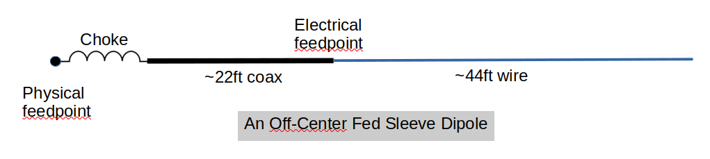
A Sleeve Dipole is a cunning idea that employs the Skin Effect to achieve a physically end-fed, but electrically center-fed dipole antenna. It comprises a quarter wavelength of coax with the center conductor connected to a quarter wavelength of wire. The braid of the coax is unconnected at its far end. Now here’s the magic: the coax braid is actually two conductors in one. Current flows along the inner surface of the braid toward the feedpoint and back along the outer surface of the braid. The outer braid surface becomes one half of the dipole, while the inner braid surface and center conductor form the transmission line. The quarter wavelength of wire is, of course, the other half of the dipole.
The transmission line is terminated at the electrical feedpoint at the center of the antenna where it is radiated. [How? My theory, as a long-in-the-tooth physics graduate, is that the signal is conducted along the plane of the space-time continuum; but back to the subject of antennas].
Current flowing in the reverse direction along the outer braid surface also needs a termination, which is arranged by means of a choke at the physical (end) feedpoint. The choke has no effect on the current flowing along the inner braid surface, but significantly attenuates the current flowing back towards the radio along the outer braid surface.
A dipole is a dipole is a dipole
Now here’s where my brain’s neurons began firing on all cylinders. A dipole is a dipole is a dipole. Ignore the magic bit for a minute. A dipole can be fed anywhere along its length nicht wahr? It is typically fed in the middle, but End-Fed Half Wave (EFHW) antennas are currently very popular among those of us who like to operate out in the Big Blue Sky Shack. An EFHW is like a dipole that is fed at one end.
Another variant is the Off-Center Fed Dipole (OCFD) that is typically fed at around one-third of its length. But the reason end-fed antennas are so popular with portable outdoor operators, such as POTA and SOTA etc, is that end-fed antennas are easier to erect in the field. Now what if we applied the skin effect magic to an OCFD, would it work?
An EFHW antenna is resonant on its fundamental frequency and may also be resonant on its even harmonics (see the post “Is an End-Fed Half-Wave Antenna Truly Multiband“). An OCFD is resonant on its fundamental frequency plus its odd harmonics. An OCFD is typically used with a “tuner” (technically an “Antenna Matching Unit”) to make it usable on multiple bands.
So, if this works, we can build an Off-Center-Fed Sleeve Dipole antenna (OCFSD) that is physically fed at one end, for ease of temporary erection in the field, but electrically fed at some other point along its length. Adding a “tuner” should allow us to operate on multiple bands.
But wait a minute … why not just use an End-Fed Random Wire (EFRW) antenna? It can also be tuned on multiple bands? Yes, but the EFRW requires a counterpoise, the OCFSD does not!
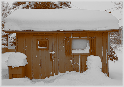
It is mid-winter here in the Great White North and Mother Nature has chosen 2025 to dump an extraordinary amount of snow on us. It ain’t easy to pop outside and throw a wire in a tree when there is an accumulation of a couple of feet of compressed icy snow on the ground and the tree branches are bowing down with the weight of the fresh snow that has fallen in the last few days. So, I built a test version to see if this idea is crazy or not. It is a short OCFSD for 20m and up. I can erect this indoors for testing purposes using my RigExpert antenna analyzer.
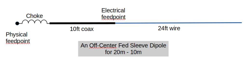
Scavenging bits and pieces from my junque collection I found 10ft of RG-174 coax, 24ft of wire, and a ham made 1:1 choke (tested using a nanoVNA: >25dB Common Mode Current attenuation) The wire was shortened to 22ft when tuning for best SWR. The SWR will probably further improve when I can get outside to erect the OCFSD properly.
“Common knowledge” holds that an Off-Center Fed Dipole has a feedpoint impedance of around 200 ohms and should be used with a 4:1 impedance transformer to provide a good match to 50 ohms. But Ham Radio Outside the Box lives in downtown Contrarian Thinkerville, so I measured the feedpoint impedance for myself. Impedance transformer? Humbug!
| Band | Untuned SWR | Untuned R ohms | Untuned X ohms |
| 20m | 2.4 | 21.2 | 5.39 |
| 17m | 10 | 9.82 | 48.7 |
| 15m | 10 | 46.4 | 140.1 |
| 12m | 8 | 78.3 | -152.3 |
| 10m | 4.3 | 57.4 | -84.5 |
If you look at the table above you can see that the measured impedances can be easily tuned with the Ham Radio Outside the Box “Old Barebones” Z-match tuner (and any other tuner in all likelihood).
| Band | Tuned SWR | Tuned R ohms | Tuned X ohms |
| 20m | 1.03 | 50.4 | 1.61 |
| 17m | 1.10 | 52.4 | 4.48 |
| 15m | 1.07 | 47.6 | -2.41 |
| 12m | 1.01 | 49.6 | -0.17 |
| 10m | 1.10 | 52.0 | 4.24 |
Both the SWR and the complex impedance values are very acceptable when measured after tuning. NB: the above measurements were taken at the physical feedpoint of the OCFSD.
What about the radiation pattern?
A inverted-V dipole has a nice donut-shaped radiation pattern with a low-angle maximum all around the circle. Great for DX and no wasted signal going straight up to warm the angels. Could it be possible that this bizarre variant of a dipole would have the same radiation pattern? EZNEC says yes, it does have a nice a donut radiation on every band although on 12m the pattern starts to develop some baby lobes in the vertical direction. These lobes become a little more prominent on 10m.
That is the state of the science on the Off-Center-Fed Sleeve Dipole at this stage. When the snow has melted and the temperature has returned from its wild swing into double digits with a minus sign in front, we’ll get this hunk of wire up in the air and see if we can make some QSOs with it.
NB: This post has been edited to comply with feedback received.

Help support HamRadioOutsidetheBox
No “tip-jar”, “buy me a coffee”, Patreon, or Amazon links here. I enjoy my hobby and I enjoy writing about it. If you would like to support this blog please follow/subscribe using the link at the bottom of my home page, or like, comment (links at the bottom of each post), repost or share links to my posts on social media. If you would like to email me directly you will find my email address on my QRZ.com page. Thank you!
The following copyright notice applies to all content on this blog.

This work is licensed under a Creative Commons Attribution-NonCommercial-NoDerivatives 4.0 International License.
Discover more from Ham Radio Outside the Box
Subscribe to get the latest posts sent to your email.

How do John
After reading your articles and very much appreciating them, I often go
back for a second helping then file in a safe place. From the
information imparted, I strongly suspect we both possess a not-so-rare
but rarely-fully-deployed OCFB (off center-fed brain).
Grabbing at new ideas, then developing and reporting on them is also a
favorite pastime of mine. The greatest reward is when, after being
told something will never work, one is then able to demonstrate that
the maligned, out-of-left-field idea in fact does work, and all along it
was there for exploitation as an extension of existing theory.
The way you described skin effect in this latest piece got me thinking
– of course, at a molecular level it will be possible to have two RF
currents, albeit at the same frequency, flowing in opposite
directions, separated believe it or not by a conductor – e.g. the
coax braid. Extrapolate that idea to wave guides where the
phenomenon can be exploited at two (or more) frequencies differing in
orders of magnitude! A vertical wave guide feeding a microwave dish
could be used contemporaneously as a quarter-wave Marconi tuned to a low
HF band, and the dish do double duty as a capacity hat.
The ramblings of a madman?
To finish off, my metabolism would not survive five minutes in your
winter environment. Truth to tell, it’s often a struggle for me to
survive at 40 degrees latitude, moderated by the sea and therefore
without continental effect. What a woos, eh?
Many thanks for your contributions and Happy New Year.
73 de Stan ZL3TK
LikeLike
Thanks for your kind comments Stan. Glad I found a kindred spirit down there in the southern hemisphere. And yes, our winters are a bit of an endurance test. Winter tires, 4-wheel drive and plenty of warm clothes get us through the long cold season. Summers are often hot and humid – but way too short!
LikeLike
Extraordinary article. I am considering this construction for a fixed installation. I have 20 free meters.
tnx
SV4ILY
73
LikeLiked by 1 person
Thank you!
LikeLike
Hi John,
I enjoy following your articles and experiments.
In this case, I want to make a technical correction to your calculation of impedances.
The “impedance” given in your table of untuned R and X has nothing to do with the SWR, or with the ability of a tune to match it. It is not the actual impedance (which is a complex number), but the magnitude of impedance.
For example, the impedances 50 +/-j0 ohms, 30 + j40 ohms, and 0 – j50 ohms, all have a magnitude of 50 ohms, but the SWR is 1 : 1 in the first case, 3 : 1 in the second, and infinite in the third. While the magnitude of impedance is commonly used in AC power engineering, there are very few times in RF work that it is useful.
For example, look at the data for 17m: the “impedance” is very close to 50 ohms, but the SWR is 10 : 1.
A more reasonable way to look at the data is to consider the R value as the impedance that needs to be matched, and the X component that needs to be compensated for in the process. Or just use the “untuned SWR” as an indicator of how difficult it may be to get a good match, as the actual impedance will vary along the length of feedline.
I’m in the middle of adding more articles on impedance and SWR to my web site at PracticalAntennas.com – hopefully within the next week or so.
Keep up with your experiments!
LikeLike
Thanks for the expert correction Dale. BTW, your comment got caught by the spam filter and I just noticed it and “unspammed it”. Hopefully that won’t happen again. I appreciate your input.
LikeLike