Imagine this: a short, vertical antenna for 20m that requires no ground, no counterpoise or radials … And … no tuner. Now, let’s add that it is only 14 feet tall and can be erected in just a couple of minutes. But wait, there’s more: it is very lightweight, slips into a shirt pocket and can be made in your own ham shack workshop in just a few minutes from a few scraps of wire.
If that sounds too good be true then well … there is a gotcha. Introducing Ham Radio Outside the Box’s Top Loaded End-Fed Half-Wave (TLEFHW). This is not a commercial product; you can’t buy a TLEFHW, you have to make it yourself. And yes, it requires no radials but it does need a “top hat” – a capacitance hat that stretches its footprint on the ground to about 45 feet.
A few weeks ago Ham Radio Outside the Box introduced the CLEFHW (Coil Loaded End-Fed Half-Wave) that uses inductive loading to increase its electrical length to a half wavelength. The TLEFHW uses the same basic idea – shrinking the physical length of the antenna – but, instead of a loading coil, we are now using a capacitance hat to achieve the same goal. The accompanying image show what it looks like.
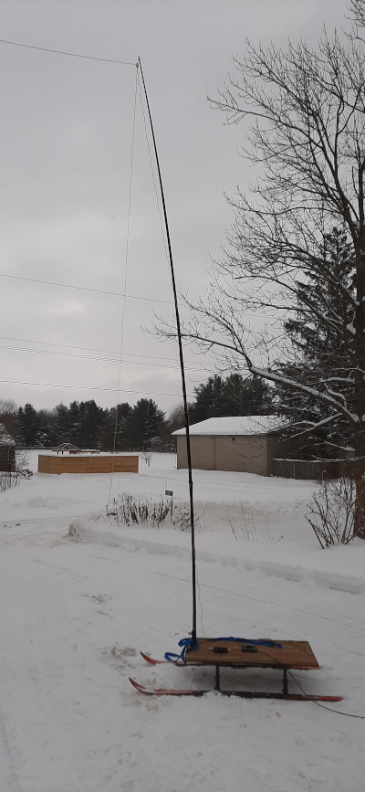
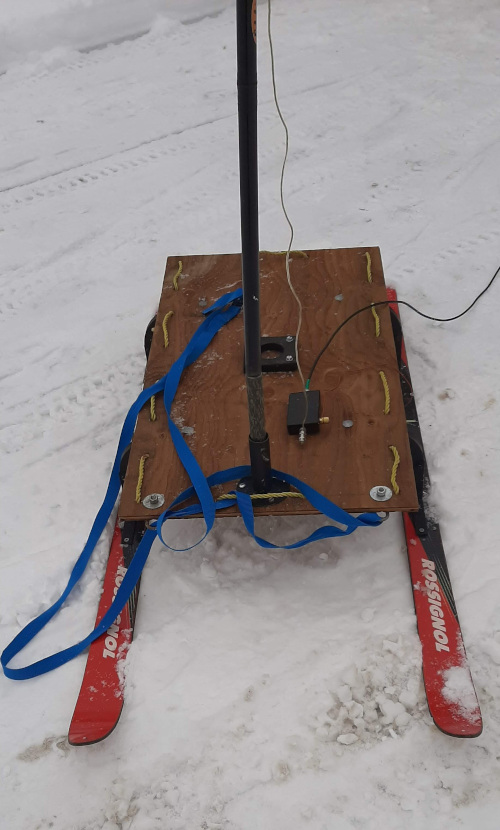
Since I mainly operate outdoors in the Big Blue Sky Shack I have mounted my kluged 14ft pole on a ham made radio sled. The way the winter is progressing here in southern Ontario suggests the sled is going to get a lot of use before spring arrives a few months from now.
Construction of the TLEFHW is very straightforward. Three wires are connected together at one of their ends. One wire (the radiating element) hangs vertically downward where it is connected to the high impedance side of a 49:1 transformer.
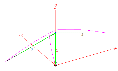
The other two wires are suspended in the shape of an inverted-V to form the capacitance hat. The wire configuration can be seen in the accompanying EZNEC diagram.
Referring to the EZNEC diagram, wire #1 is the 14ft radiating element and wires 2 and 3 form the capacitance hat. Wires 2 and 3 are each 23ft long. The pink curves show the current distribution in each of the wires. It can be seen very clearly that the current maximum is right at the top of the antenna. This means that, despite being short and low to the ground, the TLEFHW should be fairly immune to ground losses. Earthworms tunneling beneath the antenna will not risk being cooked by wasted RF energy.
Bend me, shape me any way you want me
The capacitance top hat wires shorten the vertical radiator from an electrical length of about 33ft to a physical length of only 14ft. But why was 14ft chosen? I originally modeled this antenna with a quarter-wave (17ft) radiating element and slightly shorter capacitance hat wires. My cunning plan was to employ a 17ft telescoping stainless steel whip as the radiator, then clip the top hat wires to the top of the whip. Then I erected the design in the Outback (out in the now deeply snow-covered back yard) and learned a short sharp lesson – whips don’t like having long wires hanging from the top. My whip bent 180 degrees under the weight but fortunately survived the misuse.
Several ideas were entertained for an alternative to the bendy telescoping whip and I finally settled on a kluged fiberglass pole ham made from two Crappie fishing poles that is 14ft high. This pole has some flex to it but it was designed to not buckle too much when landing a heavy fish. It laughs at two thin puny bits of wire. This same pole is also used as the center support for my Vertically Polarized 2-Eelement (VP2E) antenna. I like to standardize on outdoor field radio gear so each piece has multiple uses wherever possible.
How does the TLEFHW perform?
Like most of the Great White North, and Europe too from what I have read, this winter has been challenging so I have not been able to get outdoors to give the TLEFHW a good workout on the air. Hopefully that situation will change in the near future. For now I am reliant on computer modeling and a quick foray onto the driveway between intense snow squalls for performance data.
Here are EZNEC’s projections for the elevation and azimuth patterns for the TLEFHW:
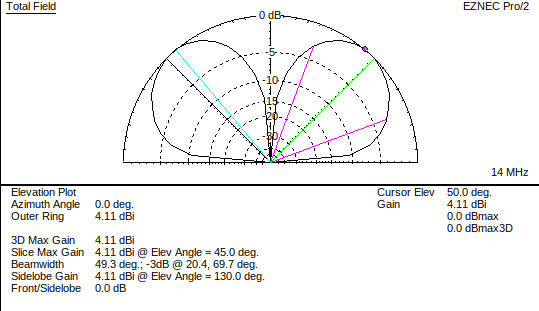
The elevation pattern shows maximum RF being launched up to the ionosphere at an angle of 50 degrees. This should give fairly good coverage over continental North America. The 3dB point is at an elevation of 20 degrees so DX signals will be only half an S-unit down compared to a dipole. A gain of 4.11 dBi is indicated which should compensate for the -3dB over a dipole.
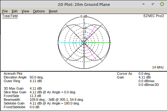
The azimuth diagram shows maximum energy being radiated in the plane of the antenna with sharp -10dB nulls to the sides. So we have a directional antenna too! From the Ham Radio Outside the Box QTH in southern Ontario, Canada, most QSOs are with stations in the United States. Since the beamwidth is nearly 110 degrees I can point the TLEFHW at Texas and cover the US coast-to-coast.
Is the TLEFHW resonant?
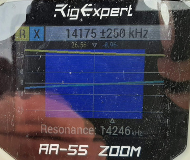
Let me preface this data with a comment: low SWR does not necessarily indicate resonance! Most hams probably tune for lowest SWR anyway and all my radios indicate SWR instead of complex impedance (R+jX). I have been using the definition (apparently in error) that resonance occurs when R=50 ohms (in a 50 ohm system) and X=0, which would yield a good low SWR. My RigExpert antenna analyzer uses a different definition of resonance to the one I have been using. According to RigExpert an antenna is resonant when +Xc = -Xl and therefore X=0, irrespective of the value of R. My thought is that the antenna will still be mismatched to the radio if R is not equal to 50 ohms. That is the distinction between resonance and SWR. I will use this definition in the future. In the image below we can see that illustrated. I apologize for the poor quality of the image; it was hurriedly taken outdoors in sub-zero temperatures in between snow squalls.
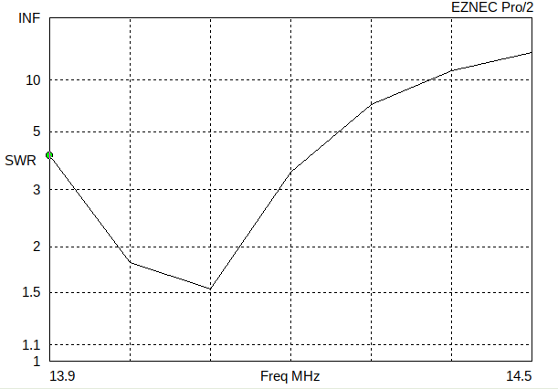
EZNEC predicts a fairly sharp SWR low at the bottom end of 20m. As a primarily CW operator I built the TLEFHW for this part of the band.
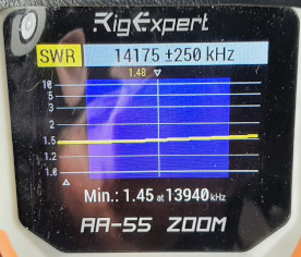
Driveway tests paint a different picture. The Rig Expert AA-55 agrees with the 1.5:1 modeling data but shows a fairly flat SWR right across the whole band. That may be an indication of a problem that has not yet been identified. If we get a break in the weather long enough for a proper field installation it may be possible to obtain better field measurements. For now, the TLEFHW shows a lot of promise as a very useful field expedient portable antenna.

Help support HamRadioOutsidetheBox
No “tip-jar”, “buy me a coffee”, Patreon, or Amazon links here. I enjoy my hobby and I enjoy writing about it. If you would like to support this blog please follow/subscribe using the link at the bottom of my home page, or like, comment (links at the bottom of each post), repost or share links to my posts on social media. If you would like to email me directly you will find my email address on my QRZ.com page. Thank you!
The following copyright notice applies to all content on this blog.

This work is licensed under a Creative Commons Attribution-NonCommercial-NoDerivatives 4.0 International License.
Help support HamRadioOutsidetheBox
No “tip-jar”, “buy me a coffee”, Patreon, or Amazon links here. I enjoy my hobby and I enjoy writing about it. If you would like to support this blog please follow/subscribe using the link at the bottom of my home page, or like, comment (links at the bottom of each post), repost or share links to my posts on social media. If you would like to email me directly you will find my email address on my QRZ.com page. Thank you!
The following copyright notice applies to all content on this blog.
This work is licensed under a Creative Commons Attribution-NonCommercial-NoDerivatives 4.0 International License.
Discover more from Ham Radio Outside the Box
Subscribe to get the latest posts sent to your email.

Nice! SleighTenna.
LikeLike
You don’t describe your matching network. Most likely it is an autotransformer, typically 1:49. Flat VSWR (when a sharp minimum is expected) indicates loss – after all a dummy load is the flattest VSWR of all. I think a lot of those autotransformers have enough loss to impact the results.
LikeLike
Thanks for the comment Chris. My matching network is wound on a FT82-43 with separate windings for the primary and secondary (2:14 turns ratio, so 1:49). The small core inevitably causes some loss. You are right that there is loss somewhere in the antenna system that is causing the flat SWR. I still haven’t been able to get outside and investigate further due to the winter weather but when I can get out I will try using another transformer wound on a larger core. This antenna was built as an experiment to investigate top loading and may not actually ever get used.
LikeLike