Almost a year ago I wrote a post entitled “A Simpler Field Expedient Rybakov Antenna for Winter“. It is worthwhile to read that post to understand why I felt it necessary to make a winter version of a proven, tried and trusted antenna. My home turf is southern Ontario, Canada about 200km northwest of Toronto. This area is sandwiched between the main body of Lake Huron and its eastern extension called Georgian Bay. Snow is almost guaranteed every winter – and often in significant quantities due to the proximity of two large bodies of water.
The antenna I built last year comprised a coil-loaded whip with an electrical length equivalent to a full-size Rybakov. Any antenna that is inductively loaded is going to be less efficient than its full-size version so I won’t debate that point. Why build a less efficient version of a Rybakov? I discussed some of the reasons in last year’s post. Let me add what I learned while doing a winter POTA activation on a Georgian Bay beach one snowy day some time ago. My antenna was mounted on my home made radio sled and required a counterpoise wire. The counterpoise was 33 feet long with a link halfway along its length to support operation on 20m and 40m. When I decided to switch from 20m to 40m I had to walk a mere 17ft and close the link. Walking 17ft (5 meters) sounds trivial, but I sank up to my knees in deep snow and I hadn’t brought my snow shoes!
We live and learn. With winter about to descend on us once again I made the decision to rebuild the Winter Rybakov, incorporating several improvements. The same Chinese 18.5ft whip has been retained, but a new loading coil of around 5 microhenries has been built for base loading the whip.
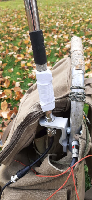
The coil is shown in the adjacent image wrapped in seasonally appropriate white electrical tape. The tape holds the coil windings in place to prevent unexpected inductance changes.
I built the coil using half-inch PVC plumbing pipe. A 3/8 x 24tpi bolt and nut was inserted at one end. At the other end a 3/8 x 24tpi coupling nut was inserted. This provides a protruding male thread at one end and a flush female thread at the other end. It was necessary to warm the pipe ends with a heat gun to get the hardware to fit.
The coil was then wound on the PVC pipe with the wire ends terminated in 3/8 inch ring terminals that fit over the threads at each end of the coil former.
In the adjacent picture you can see how the assembly comes together on my radio backpack. When the snow comes the backpack will sit atop the radio sled.
The linked raised counterpoise has been replaced with four 13ft ground radials that will not require any adjustment on the bands of interest.
How does it work?
The physical antenna length is 18.5 feet but the loading coil makes the electrical length somewhat longer. How can we determine the electrical length? First, we examine the SWR chart over the entire HF amateur radio spectrum to see where the antenna is resonant.

As you can see from the image above, there is a sharp SWR dip at 8.94 MHz. This is outside any of the ham bands so this can be treated as a random length antenna (a Rybakov is a random length antenna). You can also see a slight SWR dip near the 10m band. This is the third harmonic of the principal frequency.
We have created a quarter wavelength vertical antenna with a resonant frequency of 8.94 MHz. If we do a little simple math we can find the electrical length.
234 / 8.94 = 26.175 feet (7.98 mtrs)
So the electrical length of our Winter Rybakov is approximately 26 feet, or 8 mtrs. And that coincides nicely with the wire length of a conventional Rybakov.
Will it tune on the bands of interest?
The workhorse band for POTA is 20m but sometimes it is useful to try 40m – especially during early mornings and evenings. Occasionally there are contacts to be made on 30m as well. My low band QRP Labs QMX supports 20m, 30m and 40m (as well as 60m which I don’t use and 80m which I rarely use when portable). My old Hendricks PFR-3 QRP rig also supports 20m, 30m and 40m. I also own a Flintstones era Yaesu FT-817 (non-ND) which supports higher bands too, but I rarely use it anymore.
Oops!
To check out the 20m, 30m and 40m bands I hooked up my home made “Old Barebones” Z-match tuner and my RigExpert AA-55 Zoom analyzer. The tuner found an easy match around 1.4:1 on 20m, 30m and 40m. Just out of interest I checked the higher bands as well – no problem there either.
Then I slapped myself on the head when I realized I had forgotten the 4:1 impedance transformer that is usually part of a Rybakov antenna. After inserting a 4:1 transformer (home made of course) 20m, 30m and 40m tuned up even better.
Is the 4:1 impedance transformer really necessary?
Well, if the Winter Rybakov tunes up fine business without an impedance transformer should I venture out onto the frozen, barren tundra without it? The purpose of an impedance transformer at the antenna is to reduce SWR losses on the transmission line. However, if we add an impedance transformer there will be its insertion loss to deal with instead. So let’s examine the insertion loss of our 4:1 impedance transformer.

This is an interesting result. It shows quite a high loss (1.25dB) on the low bands but only around 0.25dB or less on the higher bands. The 4:1 impedance transformer was wound on a type 2 powdered iron core. I may have to look into trying a different core or increasing the inductance of the windings, or both. So let’s take the worst case, 1.25dB; this will result in only 3.75 watts out with 5 watts into the transformer. We are losing 25% of our power due to insertion loss. How would that compare to SWR losses arising from higher SWR without the transformer?
Let’s do the math:
Power lost (%) = (SWR-1)^2/(SWR+1)^2
Calculating for an SWR of 3:1 the power lost is 25%, the same as the transformer insertion loss. In other words, if the 4:1 impedance transformer is omitted, any SWR value over 3:1 will result in greater loss than inserting the 4:1 transformer. That seems like a clear case for using the transformer. The case will be reinforced if the transformer insertion loss can be improved on the lower bands.
Can the Winter Rybakov be made more efficient?
There is something interesting about a Rybakov antenna. It is too long on any band above 40m and too short on any band below 40m. Let’s look at the data:
| 20m | Quarter wave = 17 ft | 0.6 x electrical length |
| 30m | Quarter wave = 23 ft | 0.9 x electrical length |
| 40m | Quarter wave = 34 ft | 1.3 x electrical length |
A simple way to make it more efficient would be to change the radiating element length to make the antenna resonant on 20m and 30m (and higher bands). That’s a very easy thing to do when using a telescopic whip. A slight shortening of the whip will bring 30m into resonance very easily. Further shortening will bring 20m into resonance too.
But wait!
Just a minute; the whip is too short to be resonant on 30m without the loading coil, but on 20m it’s a whole different story. Removing the loading coil (or, more conveniently in the field, bypassing the coil with a shorting link, and shortening the whip from 18.5ft to 17ft will result in a standard quarter wave, fully resonant, vertical antenna. We’re on a roll here; what else can we do to improve efficiency?
How about lowering ground losses by raising the base of the antenna? If the base of the whip is raised by even as little as 3 feet (~1m) ground losses will be lower than a ground-mounted antenna (and the whole shebang is kept clear of the dang snow!). There is an added bonus to this idea. Instead of a compromise radial field on the ground we can use tuned raised counterpoises. A single tuned counterpoise for each band of interest can be attached to the antenna so no adjustment is necessary. I haven’t tried this in the field yet so I can’t comment on any possible interaction between the wires; they may need extra trimming.
And the door-crasher extra bonus of raised counterpoises is directivity. A radial field on the ground usually provides an omnidirectional radiation pattern which may be useful for some operators, but not for me. From my QTH I want to send most of my signal south. North of me is bear country and strangely bears are more interested in eating than ham radio (although, given the opportunity, some may be interested in eating ham radio operators).
Let it snow!
Ok, I don’t really mean that; I am definitely not a fan of winter. Short days, icy roads, trails impassable due to deep snow cover and sub-zero temperatures are not my cup of tea. But I still don my mukluks, tuque, parka and snow shoes and get out there to play radio, and this winter I will have the added fun of experimenting with my new Winter Rybakov.
Help support HamRadioOutsidetheBox
No “tip-jar”, “buy me a coffee”, Patreon, or Amazon links here. I enjoy my hobby and I enjoy writing about it. If you would like to support this blog please follow/subscribe using the link at the bottom of my home page, or like, comment (links at the bottom of each post), repost or share links to my posts on social media. If you would like to email me directly you will find my email address on my QRZ.com page. Thank you!
The following copyright notice applies to all content on this blog.

This work is licensed under a Creative Commons Attribution-NonCommercial-NoDerivatives 4.0 International License.
Discover more from Ham Radio Outside the Box
Subscribe to get the latest posts sent to your email.

John, I have an antenna that is the 10.1m +35uH coil + 1.58m . this antenna i connected to the 49:1 Xfmr . its installed as a sloper, 2 ft at the driven rnd and 25 ft at the othervend. it works great on 40m & 20M, I was wondering if it would give me the same preformance if I flipped it?
i.e. connect the 1.58m + 35 uH + 10.1m to the 49:1 Xfmrmy reasoning is the antenna is just a radiator until it’s connected to some thing there fore the Z is the same at each end. ??????
73’s
KQ4TQ
Tim
tpglennon1@gmail.com
LikeLike
Thanks for the interesting question. The 10.1m section is a halfwave on 20m. The coil plus 1.58m wire is electrically equivalent to another half wave on 20m. Altogether the antenna is electrically equivalent to a half wave on 40m. It might seem that it doesn’t matter which way round the antenna is connected but you may find the SWR changes. The reason is due to “end effect”. The 10.1m section is terminated by the coil, but if the antenna is reversed, it becomes unterminated. This usually results in something like a 5% difference in electrical length. The same will be true for the 1.58m wire. You could retune by adjusting both wire lengths or the coil inductance but, unless there is a good reason to reverse the antenna, I don’t recommend it.
LikeLike