There has been quite a lot of online discussion recently about minimizing ham footprints, reducing environmental impact and showing respect for other public space users. Parks on the Air (POTA) has been indelicately described as a 500 pound gorilla due to its immense and still growing popularity among hams. As that growth continues there is a danger that the impact on non-hams occupying the same space may lead to restrictions on our activity.
That thought has prompted me to re-examine my own portable, outdoor station and seek ways to minimize its visibility. I have written before about one incident in which a woman who stopped and expressed interest in my activity, performed a little dance when made aware of my radial wires near her feet. Since then I have resolved to avoid radials wherever possible.
No More Radials!
One way to eliminate radials is to deploy an antenna that doesn’t need them, for example, the popular End-Fed Half Wave. Actually a short counterpoise is recommended for EFHWs, but since they are voltage fed it can be as short as 0.05 wavelengths. The outer surface of the coax braid will often be a suitable alternative. An EFHW for 10m, 20m and 40m is one of my go-to antennas in the field.
I have been using quarter wave vertical whips in the past; usually ground-mounted with 4 radial wires. They have been very effective, especially on 20m where I make most of my contacts. But now I have taken another look at that choice for three reasons. First, ground mounting places the high current point at ground level where some of my signal will be lost cooking earthworms. Second, using only 4 radial wires (necessitated by the need for rapid deployment of a temporary field antenna) reduces efficiency. And, the third reason is, of course, radials increase the station footprint, in my case to a circle 26 feet in diameter.
Honey I Shrunk My Footprint
There is a way to improve the efficiency of a vertical whip and significantly reduce the portable station footprint at the same time. It is simply to raise the mounting point above ground. Multiple radials on the ground can then be replaced by a single tuned, raised counterpoise wire. Further efficiency gains can be obtained by increasing the number of raised counterpoise wires. I chose to employ 2 wires in order to keep the station footprint within 2 dimensions. Furthermore, the counterpoise wires can be sloped downwards (45 degrees is recommended to achieve a good match) thereby reducing the station footprint even more.
So far, by raising the mounting point and reducing the number of wires needed for “the other half” of the antenna we have eliminated all of the drawbacks of a ground-mounted quarter wave whip. But, can we do more? This is where it gets really interesting!
Introducing “Long Tall Sally”
If we increase the length of the radiating element (the whip) we can shorten the counterpoise wires. Now the radiating element is no longer a quarter wavelength long – and neither are the counterpoise wires. The vertical radiating element can become a random length, greater than a quarter wave, so long as the radials are shortened accordingly. How long can we make the vertical element? Modeling the antenna (I use EZNEC) helps answer that question. Can we make the vertical element very tall and shorten the two counterpoise wires enough to create a very compact station footprint? I wanted to find out and in so doing I created what I affectionately call my “Long Tall Sally” antenna (after the 1950s Little Richard song).
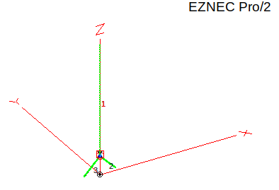
Note the two very short counterpoise wires
Long Tall Sally replaces the telescopic steel whip with a simple vertical wire 25 feet long mounted with its feedpoint 4 feet above ground. Its two counterpoise wires are each 5 feet long and slope downwards at 45 degrees to a point about 6 inches above physical (not necessarily electrical) ground. The far ends of the counterpoise wires are only 7 feet apart, so apart from the increased height (29 feet to match my fiberglass pole) the station footprint has been reduced from a 26ft diameter circle to a two dimensional footprint only 7 feet wide.

EZNEC predicts the antenna will have an SWR below 2:1 right across the 20m band. I am only interested in the CW portion at the bottom of the band, a bandwidth of less than 100KHz, but this design looks as though it should serve the phone portion of the band too.
What Kind of Antenna is Long Tall Sally?
Is she a Ground Plane antenna? Is she an Off-Center Fed vertical dipole antenna? Is she neither, but is instead some strange new animal unknown to science? I don’t know, but I do know that the prototype I built and erected in my backyard worked – I QSOd on it. How does it work? Again, I don’t know, but I am grateful to Dale, WB6BYU for his excellent website at practicalantennas.com. I am a humble antenna experimenter but Dale is a real analytical expert. I read the relevant sections of his website extensively to help me understand why Long Tall Sally might just prove to be a practical field antenna for POTA activations in tight public spaces.
Tie a Ham Antenna Round the Old Oak Tree

I feel I should mention the method of supporting Long Tall Sally (and actually my EFHW also). There is a lot of controversy about hams using trees as antenna supports. Canada has literally billions of trees and I am never happier than when I am totally immersed in the woods surrounded by them. But, I am also practical enough to understand that trees are a renewable natural resource that should be treated with respect, not reverence. We should be professional in our approach when using trees and actively seek to avoid damaging them when we use them.
Nonetheless, there are some parks in my area that have vague prohibitions on “disturbing” trees. The nature of that disturbance seems to be interpreted at the discretion of the park wardens. In those areas I use a fiberglass pole instead. If we keep a low profile and follow the rules our great hobby will continue to grow and prosper.
Help support HamRadioOutsidetheBox
No “tip-jar”, “buy me a coffee”, Patreon, or Amazon links here. I enjoy my hobby and I enjoy writing about it. If you would like to support this blog please follow/subscribe using the link at the bottom of my home page, or like, comment (links at the bottom of each post), repost or share links to my posts on social media. If you would like to email me directly you will find my email address on my QRZ.com page. Thank you!
The following copyright notice applies to all content on this blog.

This work is licensed under a Creative Commons Attribution-NonCommercial-NoDerivatives 4.0 International License.
Discover more from Ham Radio Outside the Box
Subscribe to get the latest posts sent to your email.

Hi John,
Another “no radials” vertical antenna that works well both in HF and VHF forms is the J-antenna or J-Pole antenna. The feed point has a quarter wave stub attached to it to act as “the other half of the antenna” of course this makes the antenna a single band antenna but one that can be simply rolled up, placed in a back pack and taken to a portable operating location. where it can be hung from a tree (where allowed) or supported with a fibreglass fishing pole.
73 Ed DD5LP.
LikeLike
Thanks Ed. Another variation of the J-Pole is the same basic design, but the bottom end of the wires are not shorted and become the feedpoint. When the radiator is a halfwave and the matching stub is a quarter wave it becomes a Zepp. A Zepp for 20m is part of my field antenna collection. I have tried J-Poles but since the 50 ohm feedpoint is away from the bottom I had to either use uninsulated wire or poke through the wire insulation with a pin to find the 50 ohm point. I did once make a very fine J-Pole for 70cm using a brass brazing rod mounted in a (ice) hockey puck.
LikeLike
A local German company used to produce J-antennas for all five bands 20 – 10m. I bought them all as the price was less that it would cost me to make them. unfortunately that company has now closed.
Yes, as the feed cable was strapped to the stub, there was some similarity to the Zeppelin antenna, after all on an airship, it kind of difficult to have ground radials!
It’ll be interesting to see which of all of your portable antennas performs the best on which band and which is most practical for backpacking. I keep promising myself to do that comparison with all the different portable antennas I have made and have laying around here, but I never get the time. An antenna comparison afternoon would be a great idea for a radio club activity – everyone brings a different type of antenna and they can be compared on-air.
73 Ed.
LikeLike
Is the SWR curve for Long Tall Sally relative to 50 ohms? It seems to me that the antenna is most like an off-centre fed doublet, a bit shorter than 1/2 wave long because the two short “radials” are not collinear with the long section but are spread out and approach the ground surface and thus provide some end-loading; this OCFD is being fed about 1/6 of the way from the spread-out end and I’d think the feed point impedance there would be at least a couple of hundred ohms. If that SWR curve is not relative to 50 ohms, did you use some sort of matching unit at the base of the antenna? And did you take any steps to minimize common mode current in the feedline, such as a current balun either at the base of the antenna or back at the transceiver?
David VE7EZM and AF7BZ
D
LikeLike
Good questions David. In my limited understanding of EZNEC modeling I believe it does show SWR relative to 50 ohms. I measured the SWR on a nanoVNA directly at the feedpoint and it showed around 1.5:1. I then hooked the antenna up to 25ft of RG8X (a little short of a half wavelength adjusted for velocity factor) and with minimal tuner adjustments I obtained 1.0:1 at the rig end of the coax. I used a 1:1 current balun/unun (RG-174 wound on a FT140-43 core, measured at >20dB CMC attenuation) at the antenna feedpoint. Perhaps I should check with the nanoVNA at the feedpoint again and record the actual R+jX although I recall it was mainly resistive.
LikeLike
Interesting antenna. Thanks for sharing!
LikeLike