When using a Random Wire antenna (also known as an End-Fed Random Wire – EFRW), the impedance at the feed end of the wire is usually higher than 50 ohms. In order to maintain a good match with a transceiver some form of impedance transformation is required to minimize SWR losses in the antenna system.
I read a question posted in an online forum recently asking what ratio of impedance transformer should be used: 9:1, 4:1 or something else? One of the best responses recommended a ratio of 1:1 and to allow an antenna tuner to do its job because with a 9:1 or a 4:1 transformer “impedance is all over the Smith Chart” – meaning R and X (resistance and reactance) values differ widely for each band.
I have to admit that I have followed the perceived wisdom propagated through the Internet myself in the past without really questioning the science behind it. This led me to erroneously believe that:
- 9:1 transformers are best for a random wire antennas because their feedpoint impedance is around 450 ohms
- 4:1 transformers are best for Off-Center Fed Dipoles and full-wave loops because the feedpoint impedance is around 200 ohms
- 1:1 transformera are best for dipoles because the feedpoint impedance is already close to 50 ohms
By the way, if the feedpoint impedance of a dipole is already close to 50 ohms what is the point of adding a 1:1 transformer? The answer is it provides Common Mode Current choking which stops the feedline from radiating and helps to prevent “RF in the shack”.
A 1:1 transformer may also be required in conjunction with a 9:1 or 4:1 transformer if those transformers are voltage types, as opposed to current types.
So is the perceived wisdom propagated through the Internet about which transformation ratio is right for a random wire antenna correct? I decided to find out by modeling a 9:1, 4:1 and 1:1 transformer at the feedpoint of my Rybakov antenna using EZNEC.
My Rybakov antenna has worked very well for me in several POTA activations. Following the advice of others I used a 4:1 transformer at the feedpoint. The antenna comprises a 28.5 radiator supported by a 29ft vertical telescoping fiberglass pole. Its feedpoint is at the base and there are four 13ft radials spread out orthogonally along the ground. I used this antenna in my modeling because it is the antenna I use most often for outdoor portable operations. The results are specific to this antenna and may differ for other random wire configurations.
The object of the exercise was to find out which transformation ratio works best for this antenna. A random wire antenna is not resonant on any band and requires an antenna tuner to operate. I modeled the Rybakov over a frequency range of 7-30MHz for each transformer ratio and plotted the results on a Smith chart and as an SWR chart. It is easy to see from the diagrams below that the impedances for each band are indeed “all over the Smith chart”. We can also see whether the SWR for each band falls within reasonable tuning range for an ATU.
9:1


The results for a 9:1 transformer show a very high SWR on 40m, but an easily tunable value on all the other bands. Even 40m should be tunable, except perhaps by some transceiver internal tuners with a limited tuning range.
4:1


The results for a 4:1 transformer are very similar with 40m once again being the outlier, but still tunable by most ATUs.
1:1
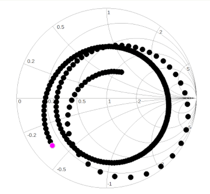

As predicted by the answer to the “which ratio?” question on the forums, a 1:1 transformer ratio yields the best overall performance across all the bands. While 40m remains the highest SWR it is still less than 10:1, with all the other bands falling between 3:1 and 7:1. My Rybakov radiator wire is only 28.5 ft long which is short for 40m.
I carry a 1:1 transformer in my field kit so I can safely deploy it instead of the 4:1 I used previously. And, away from the computer simulation, back in the real world, does it work in practice? My LDG Z-11 Pro ATU handled all the bands easily. Did I make any QSOs with the Rybakov with a 1:1 transformer? Yes indeed; I completed a POTA activation with it and even logged some DX stations.
Notes:
- I have used the term “transformer” throughout this post. A random wire antenna worked against ground is an unbalanced antenna. A coax feedline is naturally unbalanced, so the term “unun” could also be applied.
- The transformation ratios are impedance ratios, not turns ratios. Impedance ratios are equal to the square of the turns ratio.
- Impedance transformers are wound on a powdered iron toroid core (type 2 or 6), or a ferrite toroid core (e.g. type 31 or 43).
- 1:1 transformers are more commonly called Common Mode Current chokes.
- All the Smith Charts and SWR diagrams shown above are for the antenna only. The feedline may change the impedance seen by the transceiver. It always wise to test a complete antenna system before taking it out to the field.
- Once again, these results are specific to my own Rybakov antenna. Any other antenna may produce different results. It is strongly recommended to do your own research to find out what works best for your own antenna system.
None-to-None?
In the title of this post I mentioned “none-to-none”. Of course there is no such thing, but the term implies the absence of any transformer. It is possible to omit the transformer, or CMC choke particularly when operating QRP where the common mode current will be very small anyway. If the antenna is worked against ground-mounted radials any feedline radiation will be absorbed. RF in the shack for a QRP operator can be minimized by using a long feedline.
Conclusion
You can’t believe everything you read on the Internet, but sometimes an idea published online can trigger a question in your mind that demands an answer. The best way to answer such a question is to do your own research and follow your own conclusions. That advice applies to this blog too. What works for me may not work for you. Constructive comments are always welcome on hamradiooutsidethebox.ca. If you have alternative ideas – or questions – please post them here; I would be pleased to discuss them with you.
Discover more from Ham Radio Outside the Box
Subscribe to get the latest posts sent to your email.
