Let me start by confessing; I don’t operate HF mobile. So my “mobile” HF antenna is only suitable for stationary “shack-in-a-truck” operations. Driving requires my full attention … and so does CW operation!
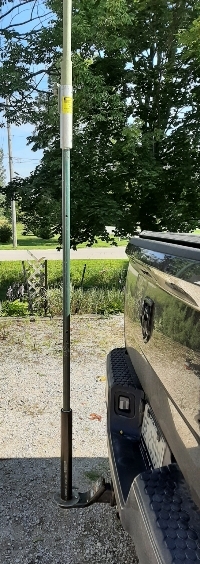
I mount one of my two portable vertical antennas on a short aluminum pole which in turn is mounted on the hitch of my truck. My two portable vertical antennas are an MFJ-1979 17ft telescopic whip for 20m and up, and an adjustable centre coil-loaded Buddipole 9ft telescopic whip that can be used down to 40m.
When I first started using these antennas on the truck, I attached a raised, tuned counterpoise wire for “the other half” of the antenna. Then, one day, being a tinkerer, always willing to try something different, I asked myself whether the truck chassis would serve as a counterpoise. If it worked I could dispense with the counterpoise wire and make setting up the shack-in-a-truck a little simpler, as well as reducing the footprint and making the station entirely self-contained.

Paint it Black
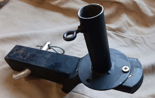
Well I tried and it worked. Without any additional wire counterpoise and without a tuner, I obtained an SWR around 1.5:1 on 20m and 40m. There is a DC path from the shield side of the SO-239 antenna connector, down the short (about 3 feet) aluminum pole to the hitch mount. But, is there a DC path through the hitch mount to the hitch receiver and thence to the truck chassis? The hitch mount is painted black (Sir Mick Jagger would approve of that, hi hi). I checked with a continuity tester and found no conductive path through the painted hitch mount to the hitch receiver.

Both mating surfaces show signs of rust so there may be serendipitous conductivity between the two where the paintwork is damaged. The shack-in-a-truck antenna works reliably every time I use it. If a conductive path between the hitch mount and the hitch receiver were based on the chance mating of small patches of bare metal it surely would not be reliable.
Aha – Of Course!
After spending some time in my reclining thinking chair, inscribing ideas on the back of my eyelids, another thought sprang to mind. My operating position in the back seat of the truck is connected by a 29ft length of RG-58 coax, thrown in haphazard fashion across the plastic tonneau cover of the truck bed and then directly attached to the SO-239 at the base of the antenna. It was a “lightbulb” moment. “Of course” I thought, “the coax shield is acting as the counterpoise!”
It seemed to make sense; 29ft of coax shield should make a fairly good counterpoise for 20m and 40m. There was a simple way to find out if that was, indeed, what was happening. I disconnected the coax and inserted a common mode current choke at the antenna end. For simplicity I usually omit the choke. my field portable kit has a choke at the rig end to act as a line isolator. The rig end choke blocks both common mode currents and any induced RF on the coax shield.
I had measured both chokes as I described in a previous post. They were constructed of FT-240-43 toroids (I know, type 31 would theoretically be better) wound with RG-58 coax. The number of turns was adjusted until a common mode current (CMC) attenuation of better than 30dB from 3-30MHz was obtained. With one of these chokes blocking any CMC from travelling down the coax shield, the only other route was through the hitch to the truck chassis.
What A Surprise!
I keyed up the radio and confidently expected a high SWR. The truck was parked on my concrete driveway and without the CMC choke I measured an SWR of 1.3:1. To my surprise I saw the SWR had dropped, ever-so-slightly, to 1.2:1 with the outer surface of the coax shield isolated from the ground path. Well, that was a surprise!
So, if the coax wasn’t acting as a counterpoise, I was back to trying to discover where the ground path for the antenna was going. I had established that there was no reliable DC conductivity between the hitch mount and the hitch receiver. Both surfaces show some rust and, as allied POWs in the Second World War discovered, rusty steel can be used as a semiconductor. [The POWs “tickled” the surface of rusty razor blades to make a crude RF detector].
Now It Gets Complicated
Introducing a crude, unpredictable semiconductor into the ground path is too complex to attempt to evaluate so I eliminated that from my inquiries. The only remaining possibility was a capacitive connection between the hitch mount and hitch receiver. The truck has a 2-inch hitch so there are four surfaces each 2 inches wide by about 4 inches long; that’s 32 square inches on each “plate” of a “hitch capacitor”.
I plugged these numbers into an online calculator to find the capacitance of the connection. A parallel plate capacitor has a value derived from the formula C=(dielectric permittivity x plate area) / plate separation. The value for my shack-in-a-truck antenna is 72pF.
Using the formula XC=1/(2*pi*F*C) yields a capacitive reactance of 157 ohms on 20m and 313 ohms on 40m. Sounds a little bit too high for a good ground path doesn’t it?
If It Works, It Works
Did I take this analysis a little too far? I don’t think I am any closer to getting a clear answer to why my shack-in-a-truck vertical antenna works. Perhaps I should just follow the time-honored principle of “if it works, it works”. Just get on with making QSOs and don’t question the magic!
One thought on “A Magic Ground Mobile Antenna”