What is common mode current? It is the current that flows along the outer surface of your coax shield from your antenna back towards your radio. It can cause SWR problems, erratic behaviour of radio equipment and even RF shocks when you touch metal parts of your rig.
A coax cable has three conductors! Due to the “skin effect” current can flow along the inner surface of the coax shield as well as the outer surface. The job of a common mode currrent choke, CMCC, is to impede the flow of common mode current along the outer skin of the shield without impacting current flow on the inner conductor or inner surface of the shield.
A CMCC can also be described as a 1:1 balun. Take the example of a dipole antenna connected to the radio by a coax cable. A dipole is a balanced antenna but a coax cable is inherently unbalanced. The job of the balun is to connect the two together while reducing common mode current.
How many times have you heard the advice to coil a few turns of coax at the antenna end to form a choke. Does it work? Typical “scrabble wound” chokes are unpredictable. Some sources say they may even make the problem worse.
Let it Flow!
For most of the summer of 2022 I have been using a vertical antenna with four ground-mounted radials for my rapid deployment Parks On The Air (POTA) antenna. It is usually advised to place a CMCC at the base of a vertical antenna to prevent common mode currents flowing back towards the radio. But there is another way of looking at that. I chose instead to use the coax shield as a fifth radial. I will explain why.
You see, there is another potential problem. Spurious RF could be picked up by the RF shield. That can sometimes be avoided by careful routing of the coax so that it is not in the near-field of radiation from the antenna. But it can be stopped by a choke at the radio end of the coax. Good advice might be to have a choke at both ends of the coax. I carry a second CMC choke just in case it is needed.
So if a scrabble-wound coax choke is unreliable, what should be used instead? A few turns of coax wound through a large diameter ferrite toroid core is better. But even this solution has hurdles to overcome. Which ferrite mix should be used? How many turns of coax is right? The best ferrite for HF use is type 31. But, as it happens, I had several type 43 cores available so I decided to employ them instead.
My initial approach was to take a coax cable from my collection and wind as many turns as would fit around a FT240-43 (2.4 inches diameter, type 43 mix) toroid. Then a fellow club member advised me to consider reducing the number of turns. He was right!
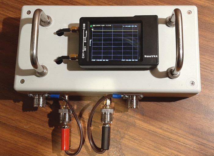
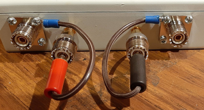
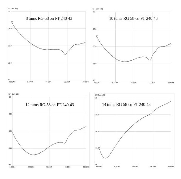
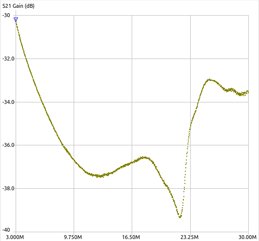
I had built a jig for my nanoVNA to make CMCC analyses easier (see pictures). When I measured the CMC attenuation of my choke I discovered it worked brilliantly (>30dB CMC attentuation on the low bands) but its effectiveness dropped off sharply on the higher bands.
The choke had 14 turns of RG-58 cable wound around the core. I reduced the number of turns, two at a time, and measured the impact. The attached graphs showed the dramatic changes in attenuation as I reduced the number of turns from 14 to 8. I settled on 12 turns as the optimum for my desired bands.
Oh no, another variable! After finalizing the design I discovered the orientation of the turns and their spacing changed the attenuation versus frequency curve. It is often desirable to have a “crossover turn” to make the coax enter and leave on opposite sides of the toroid. However, this – and the turns spacing changed the inter-turn capacitance and the frequency response of the choke.
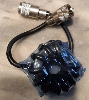
After some fiddling with the turns and several re-scans of the choke I secured the turns with zip ties and shrink sealed the choke using my favorite poor man’s shrink wrap – a plastic water bottle with the ends cut off. Sounds crude but it really works. As the plastic shrinks it hardens, not only locking the turns in place but providing physical protection too. Ferrite toroids are brittle and field operations can be harsh on vulnerable equipment.
After all was done I placed the CMCC on the test jig one more time and discovered it had changed again – for the better. It was only a slight improvement but the final choke has a CMC attenuation of better than 30dB from 3 to 30MHz.
A final note about my CMCC jig. The nanoVNA (I have the tiny H version) is a fabulous and inexpensive piece of test gear. It is also very fragile. One of its greatest vulnerabilities is the fragility of the SMA connectors giving access to its two ports. My home made jig provides a simple means of connecting big PL-259 connectors to tiny fragile SMA connectors without physically stressing the latter. Note that for CMC measurements, the two ports of the nanoVNA are connected to the shield at each end of the coax winding of the choke. My deteriorating eyesight makes it difficult to read the tiny screen of the nanoVNA-H so I used the really good nanovna-saver software on my Linux Mint laptop.
I don’t pretend to be an expert on common mode current chokes. I have been learning from others as I work my way through developing what works for me. I owe a debt of gratitude to all the others – too numerous to mention – who have shared their knowledge online. I hope my humble contribution will add a little to the store of knowledge on the subject. Your comments, suggestions and error corrections are welcome.
Discover more from Ham Radio Outside the Box
Subscribe to get the latest posts sent to your email.

I made a current choke using 240-31 mix and gave it 10 turns at first I used RG8X and a comment on the blog warned me about this coax turn radius and I may have overshot the maximum. I then moved to some RG316 coax and used that. I don’t have the nano VNA to fine-tune things but I hope it is doing the job.
73,
Mike
VE9KK
LikeLike
Thanks for the comment Mike. I bought a big reel of RG-58 at an auction several years ago. RG58 wouldn’t be my first choice but it works and it seems to handle tight turns around an FT240 core ok. I have some short RG-316 cables for my nanoVNA. I’ll have to maybe source some more of it.
LikeLike
Hello Dear,
I just read your article.
Interesting experiment.
However, it must be considered that a choke balun is really operational when it is inductive.
It will therefore be necessary to take care to see the phase to determine in which range your choke is inductive and not capacitive.
You can see this by winding a simple self.
Also by comparing the attenuation with a resistance on the transmission measurement, you can approximately determine the equivalent resistance.
Hope this helps in your testing.
LikeLike
Thanks for your contribution and the very helpful tip. This is a complex topic and I documented a simplified test procedure that provides some assurance of a choke’s effectiveness. There is probably much more that could be added to the store of knowledge on this topic. I hope others will also come forward to provide their insights.
John VA3KOT
LikeLike