Field expedient antennas differ from home-based, permanent antennas. At a home QTH there is often plenty of room to install a larger, higher antenna. In the home shack, the radio is often capable of putting out a much more powerful signal than a field radio.
Out in the field, for example at a campsite, space may be limited and suitable antenna supports (such as trees) may not be in the right place, or of sufficient height. The antenna must also be rapidly deployable and not damage or interfere with the environment. Transmitter output power may be limited by battery capacity and it may be essential to keep equipment weight low, so an external tuner may not be available.
It is also advisable to practice stealth in public spaces; park officials and the public may be suspicious of ham radio installations. A very long wire antenna up in the trees should blend in with the foliage. Invisible antennas do not attract unwelcome attention.
When I am camping in provincial parks I try to erect my Shorty End-Fed Half Wave antenna for 80m so that I can check-in to a weekly CW net. This antenna also gives a usable SWR (<3:1) on 20m and 40m (and possibly 10m and 15m too although I don’t often use those bands). I have a home-made L-match for fine tuning but I try not to use it to save weight.
No two temporary field installations of the same antenna give the same results due to differences in ground conductivity, height, orientation etc.
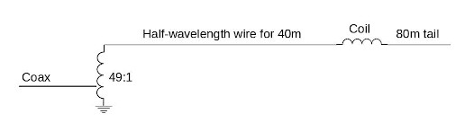
My Shorty 80m EFHW comprises a 49:1 autotransformer (to match the very high impedance at the end of a half-wave wire), a half-wavelength wire for 40m (also a quarter-wavelength for 80m), a loading coil and a short tail wire. The coil and the short tail wire (about 6 feet) make up the other quarter wave on 80m.
If I need to reduce the length of the antenna to work the 40m band you might expect that I could just disconnect the coil and tail wire leaving a “half-wavelength wire for 40m”. But no, that doesn’t work!
Why doesn’t it work? The answer is actually very simple; it is due to the Weird Antenna Wire End Effect that I wrote about in a previous post. When the “half-wavelength wire for 40m” is terminated by the coil its electrical length is longer than when the coil is disconnected.
Using the usual formula 468/f to calculate the length of a half-wave wire for say 7.030 MHz gives a length of 66.57 feet which is too short if the wire is terminated by the coil. So we must use the alternative formula 492/f which gives a length of 70 feet.
If we just disconnect the coil and tail wire to get a shorter antenna to work the 40m band, our antenna will be too long and the SWR will be higher. So the wire must be shortened by 70-66.57 = 3.43 feet to bring it into resonance.
Can we now use this half-wavelength wire for 40m to work the 20m band? 20m and 40m are harmonically related so in theory the answer is yes. In practice, the Weird Antenna Wire End Effect comes into play again.
The 49:1 autotransformer is expecting to see a half-wave wire but, on 20m, it is seeing two half-waves end-to-end. The first half-wave is terminated by the second half-wave so its length (492/f, where f is 14.060 MHz) should be 35 feet. The second half-wave is unterminated so its length (468/f) should be 33.28 feet. The total length expected is 35+33.28 = 68.28 feet.
Our half-wavelength wire for 40m is 66.57 feet long – too short by 1.71 feet. Perhaps the best solution (the one I have adopted) is to carry a separate half-wave wire for the 20m band. Now, we have a conveniently short antenna. The wire is unterminated and is (468/f) 33.28 feet long.
One important point to note: In the real world resonant antenna lengths rarely exactly coincide with calculated values. It is usually necessary to make wires a little too long and tune them by folding back part of the far end until lowest SWR is obtained.
How to find the length of the 80m tail wire and the inductance of the coil? This is probably the easiest part of the design. Decide how long you would like the tail wire to be then use online calculators like those at 66pacific.com to find the required inductance and the design of the coil. The coil and tail wire can be treated as a base-loaded quarter-wave antenna. Just plug in the numbers and watch the magic!
The Build: There are many options available for purchasing a commercial End-Fed Half-Wave antenna. I prefer to build my own. If you are like me you can probably figure out how to build one yourself with a bit of guidance from numerous YouTube videos and antenna forum posts on social media.
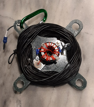
AUTOTRANSFORMER: I built my own 49:1 autotransformer on two stacked FT-140-43 toroids (Mouser Electronics) using a 3:21 turns ratio. FT-240-43 toroids are usually recommended but the stacked, smaller toroids fit nicely on a wire winder. I do not use the recommended high voltage capacitors across the input. I tried them but they made no difference in performance.
LOADING COIL: Using inductance values and dimensions obtained from online calculators I wound my loading coil using the same wire I used for the antenna. I found a scrap piece of lightweight plastic tube from a built-in vacuum cleaner installation for the coil former. As you can see from the picture, I added strain relief on both ends of the coil to prevent the connections from working loose or breaking. I wrapped the coil with self-bonding plastic tape (plumbing supply stores) to protect it from bird poop, squirrels, tree sap etc.

Whether you choose to build or buy, good luck with your antenna!
Discover more from Ham Radio Outside the Box
Subscribe to get the latest posts sent to your email.

Your antenna when adjusted to be effectively a half wave long on 40 m is too short for 20 m, with anti-resonance at say 14.6 MHz. To make 20 m happy without disturbing 40 m, somewhere near the middle of the wire (ideally, wherever the current maximum and voltage minimum occur on 40 m) hang an additional short vertical wire. This is a low impedance point on 40 m so there will be little effect. But on 20 m you are near a current minimum and voltage maximum so there will be quite a big effect. Adjust the length of this short vertical wire for optimum results on 20 m.
It may help on 10 m too though its length and placement won’t be quite optimum. On 15 m it will be located near a current maximum and voltage minimum so unfortunately it will do little good (nor harm).
It’s about an eighth of a wave from the near end, on 80 m, so it will upset things there somewhat, but I would assume by adjusting the inductance of the loading coil near the end of the antenna and/or the length of the final short section past the loading coil, you could bring 80 m back where you want it to be.
David VE7EZM and AF7BZ
LikeLike
Thanks for the comment David. I use a full length 80m EFHW at home. The coil-loaded EFHW gets used when I am camping. I don’t get on 80m very often except for a weekly CW rag chew with friends. I would like to study your idea more carefully to make sure I fully understand all its ramifications. Detailed technical suggestions like this are very welcome on this blog.
LikeLike
The trick I suggested will work to make the thing work better on 20. If you use a full sized 80 m 132 ft EFHW you can use the same trick to make it work better on 40, 20, 15, and 10. Just hang the extra wire at the high current point on the low frequency band where it will be ignored and adjust its length to make it work better on the harmonics. Costs next to nothing and it can really help.
LikeLike
A quick question comes to mind David. I can foresee that the vertical wire would be affected by wind, perhaps to the extent of wrapping it around the main antenna wire. Have you used this technique yourself? Is there a way of securing the vertical wire to prevent this?
LikeLike
Extend the vertical wire with a thin string all the way to the ground and tie it to a handy bush or rock or drive a small stake into the ground. I would just use whatever comes to hand on whatever hill I find myself, assuming this is a temporary installation.
I got the idea from W5DXP who a long time ago had a web page discussing the same problem arising with a 7 MHz center-fed dipole used on 21 MHz. The dipole resonant on 40 m was resonant outside the high end of 15 m and by attaching such additional wires about 11 ft either side of center (he used two of them because of symmetry of the dipole) he could bring the 15 m resonance down into the band without too much effect on the 40 m resonance. These wires weren’t at the high current low voltage point on 40 m but they were only about 1/6 of a wavelength away from that point so they didn’t disturb 40 m very much. Placed right at the lower frequency high current low voltage point they will have even less effect of the lower band.
What you are doing is capacitively “end-loading” inner half-wave sections of the antenna on the higher frequency band, sections where the end-effect would otherwise be absent, and if you can do this far from high voltage points on the lower band there won’t be much interaction.
LikeLike
Change “1/6 of a wavelength” to “1/12 of a wavelength”. Never expect a retired mathematician to be able to do arithmetic correctly in his head.
LikeLike
Very interesting article on the EFHW antenna. Will have to give it a try as that is the only antenna I have never used!
LikeLike