I have posted before about my DIY vertical antenna. It is a rapid deployment antenna that has served faithfully for several POTA activations. But, recently I came to realize it wasn’t meeting my needs for all three ways in which I needed to deploy it. Time for a redesign!
My vertical antenna is a centre-loaded unit with three use cases:
1 . Mounted on a hitch mount on my truck . This mount is not intended for mobile use; the antenna is not ruggedized for high speed motion. But, where deployment in a paved parking lot is called for, this mounting method allows the truck chassis to serve as “the other haĺf” of the antenna

2. Mounted on my “Wireless Wagon” (a lightweight hand cart). Where it is necessary to move equipment a moderate distance over grassy or unpaved terrain the Wireless Wagon becomes extremely useful. It provides rapid deployment antenna support and radial connection points without any penetration of the ground being necessary.

3. Mounted on a trekking pole for pedestrian mobile operations. If equipment needs to be backpacked over rough terrain, a modified aluminum trekking pole can support the antenna. The pole can be handheld or pushed into the ground.
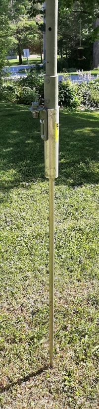
In all three use cases the common issue is providing a convenient path to ground. A vertical antenna is usually a quarter wavelength long and needs another quarter wave element to provide “the other half”. My preferred method of providing the other half – when operating a temporary outdoor station – is ground mounted radial wires.
In use case 1, the truck hitch mount provides a capacitive path to the truck chassis and no other radials or counterpoise are required. In use case 2 the aluminum frame of the Wireless Wagon provides a ground path to the radial wires. In use case 3 the aluminum trekking pole provides a ground path to the radial wires (or a drag wire).
The original antenna design employed a plastic Schedule 40 threaded connector to isolate the antenna driven element from ground. A single counterpoise wire provided “the other half”. The counterpoise wire was attached to the barrel of the coax connector by a large alligator clip while the coax centre conductor was connected directly to the antenna driven element.
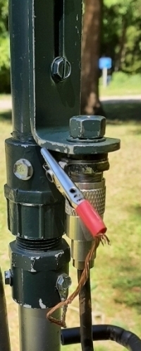
In the redesign this arrangement was replaced by three concentric tubes. The inner aluminum tube is the driven element while the larger diameter outer aluminum tube is the ground connection. Each conductive tube is insulated from the other by a short section of 3/4 inch Schedule 40 PVC tube.
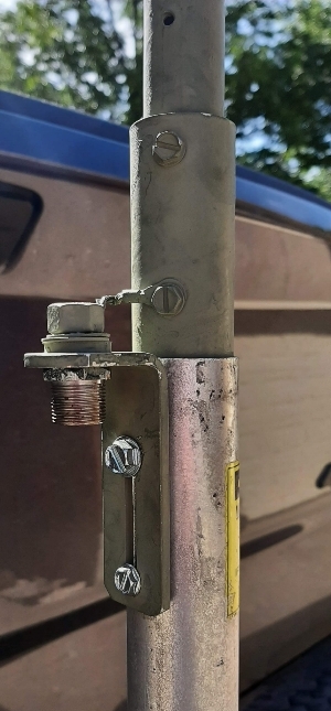
Now, the coax centre conductor is connected to the antenna driven element by a very short wire while the coax shield is directly connected to the outer, grounded tube. This arrangement provides a direct conductive path to ground in all three use cases.
The redesigned vertical antenna has already proven successful in the truck hitch mount and Wireless Wagon use cases. Maybe this redesign will stick around, or maybe not; I do like to tinker with new ideas so who knows!
Discover more from Ham Radio Outside the Box
Subscribe to get the latest posts sent to your email.

One thought on “Vertical Antenna Redesigned”