For the last several weeks I have been experimenting with ideas for low impact field antennas that optimize stealth, rapid deployment and small footprint while maintaining efficiency. It’s a trade-off between size, portability and efficiency. The antenna that is very small, highly portable and very efficient hasn’t been invented yet – and never will be invented because it would defy the laws of physics.
Some hams may hold the belief that a short, base-loaded whip defies physics because (1) it can be tuned to 1:1 SWR, and (2) it can be used to make contacts. On the right day, under favorable propagation conditions even a wet noodle makes a “great antenna”. I have personally made contacts with a dummy load (across a room during a technical presentation). A 1:1 SWR ensures a transceiver won’t release the “magic smoke”; it does not make a poor antenna work any better.
Oh yes, I’m the great pretender …
The Platters (love those songs) could have been singing about ham radio tuners. Internal tuners, or any tuner located at the radio end of a feedline is a great pretender. It pretends the antenna is doing well when really its only job is to convert the impedance of the antenna, and feedline, into something that won’t vaporize those little 3-legged fuses that we like to call PA transistors in the transceiver.
For this reason I prefer to avoid using a “tuner” at the radio end of the feedline. A tuner has a role to play when using a multiband antenna (such as a random wire), but a monoband antenna can be adjusted to resonance (or close to resonance) thereby avoiding any need for an impedance transformation at the radio end of a short feedline. For example, a simple resonant whip mounted on a pole a couple of meters above ground, with two or more resonant radial wires does not require a tuner. But there’s a gotcha.
High wire act – danger, danger!
I was playing radio in a provincial park once when my wobbly whip attracted the attention of a patrolling park warden. Her job included preventing mad boffins with dubious aerial erections from endangering other park users. I was able to persuade her that my activities were unlikely to trigger the arrival of emergency services and all was well. That experience convinced me of the value of operating stealthily by staying under the radar of anybody who may look on my activities with suspicion. Lesson learned – low antennas equal low attention.
The Dancing Queen
I have told the tale of the dancing lady several times on Ham Radio Outside the Box. My unusual activity attracted her attraction and she approached to inquire what I was doing. When I advised her to be careful of the long radial wires on the ground she broke into an impromptu and erratic dance routine. Lesson learned – long radials are where angels fear to tread.
When the twilight is gone, and no songbirds are singing …
My wife and I have been putting out bird feeders in our back yard for quite some time. The feeders have attracted many different kinds of birds, prompting us to learn more about their behavior and habitat. One of the important things we learned is that trees are birds’ safe place. It is where they shelter and nest. Lesson learned – avoid invading their space by firing projectiles and dragging long wires through it.
Park wardens licking their pencils ready to write out an infraction ticket, dancing queens dodging wiggly wires, and fishing weights landing in bird nests … by all the ancient Norse gods, what’s a poor ham to do? Those were the design parameters I had to work with. Could it be done? Could I design antenna that will fit into those restrictions? The Devil was dangling a short base-loaded whip in front of my eyes but I banished him. No, that is not the solution!
So what is the solution?
There are inevitably many solutions to this puzzling conundrum and each may work in some fashion. One contender is something I have come up with and called a “Ladder Line Antenna”. Ladder Line (sometimes referred to as “Window Line”) is usually used as a feedline but it doesn’t have to be so. Ladder Line is simply two conductors separated by plastic with a series of rectangular holes. It resembles a ladder, or looked at differently, it could be seen as a series of windows.
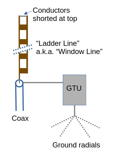
Why use Ladder Line as the antenna’s radiator? Because, to reduce the overall height of the antenna by around 30% the antenna is linear-loaded. Linear loading is the technique of folding back the radiating element and can be achieved by shorting the two ladder line conductors at the top. The far end of the folded side of the radiator is left unconnected. The radiator is connected to the coax center conductor.
The overall length of the Ladder Line radiating element for my 20m band antenna is approximately eleven and a half feet (three and a half meters). It was trimmed while measuring its electrical length with an antenna analyzer.
Banishing the Dancing Queen
Understanding that long radials for this antenna are strictly verboten creates a bit of a problem. Usually, a set of ground mounted radial wires are employed with a vertical antenna and a tuner is used at the radio end of the feedline to match the impedance.
No matter how many radials are laid down they will not be resonant. And, the use of a tuner has been ruled to be equally verboten. But there is a solution and that is to use a GTU (Ground Tuning Unit) to increase the current in the radial system, making it appear resonant. To keep the Dancing Queen at bay I shortened the radial wire length to 7 feet (a little over 2 meters) and used eight radials. The radiating element has already been adjusted for resonance so now is the overall antenna resonant? Well not quite.
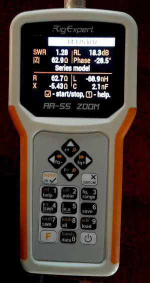
You can’t cheat physics. Eight short radials, even when “tuned” with a GTU are not resonant. My experiments with a square meter of Faraday cloth proved that principle. There remains a small reactive component to the antenna impedance as can be seen in this image of the antenna analyzer reading when connected by a very short length of coax.
The reactive component, in this case 5.43 ohms of capacitive reactance, could have been reduced further by careful adjustment of the GTU. Unfortunately, the GTU is difficult to adjust precisely and hand capacitance also affects the adjustment. Another challenge for brainy boffins to overcome. The impossible done at once, miracles take a little longer!
Is a linear loaded antenna efficient?
L.B. Cebik W4RNL(SK) published a series of articles on shortening HF dipoles. He established that dipoles remain quite efficient down to 10% of their full length. However, below 70% the complex impedance becomes increasingly difficult to match. My simple ladder line antenna is shortened to approximately 70% of its original length.
The real world test
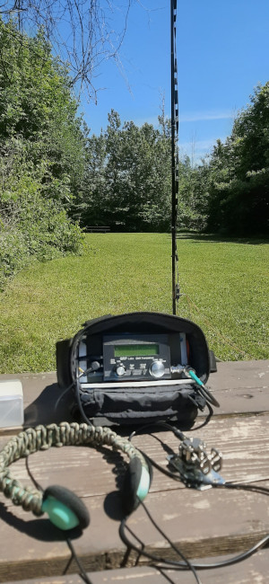
Following several sessions out in my backyard, hunting POTA stations, I figured the antenna was ready for the real test. Could it work well enough for a QRP CW POTA activation?
I had two activations planned, each in separate locations. During the first activation, propagation conditions were a little difficult with a lot of signal fading (QSB). Stations would disappear into the noise then, seconds later, come back bending the needle on the signal strength meter. It took an hour to log 13 stations, but with the furthest being 1876 km away it showed the short, low profile antenna had good potential.
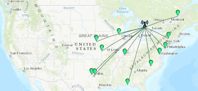
The second activation a few days later showed even better results.
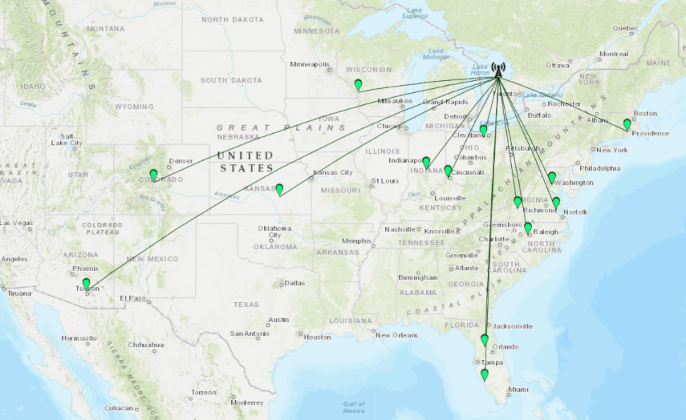
Propagation conditions were better this time around and contacts were made in Arizona, nearly 3000 km away from my QTH on the Canadian shoreline of Lake Huron, Colorado (2200 km) and several others close to 2000 km. It was also interesting to note that some of the contacts made were less than 1000km away. This means the antenna is capable of radiating signals at a broad range of take-off angles.
Overall I am very pleased with this simple, low profile antenna. It can be supported on a very lightweight 13 ft high pole that mounts on a small stake in the ground in summer, or a compact tripod when the ground is frozen in winter. The eight 7 feet long radials take the longest to deploy and occupy a circular footprint of 14 feet. An alternative I am working on involves a single raised linear loaded radial to replace the ground radials. This will reduce the footprint to two dimensions and make the antenna suitable for deployment on a narrow trail. I am also working on a multi-band version of this antenna. More details to follow in a future post; stay tuned.

Help support HamRadioOutsidetheBox
No “tip-jar”, “buy me a coffee”, Patreon, or Amazon links here. I enjoy my hobby and I enjoy writing about it. If you would like to support this blog please follow/subscribe using the link at the bottom of my home page, or like, comment (links at the bottom of each post), repost or share links to my posts on social media. If you would like to email me directly you will find my email address on my QRZ.com page. Thank you!
The following copyright notice applies to all content on this blog.

This work is licensed under a Creative Commons Attribution-NonCommercial-NoDerivatives 4.0 International License.
Discover more from Ham Radio Outside the Box
Subscribe to get the latest posts sent to your email.

It’s tempting to try it today. My last ladder line experiment left me with an abundance of such stuff. Yet, my only operable mast is carbon fiber and I’m skeptical of its interference. Lessee,,, is the remainder of that busted up fiberglass mast long enough?
THANKS for the ideas, John
72 de N4REE Bob
https://bob-easton.com/n4ree
LikeLike