Everybody knows That’s how it goes Everybody knows
Everybody knows loading coils are lossy so it must be true eh? No need to question what “everybody knows” – unless you think outside the box. Well, that’s the primary mission of this blog so let’s take a look at the proposition that “loading coils are lossy” and use some critical thinking so find out if “everybody” is right or …
How to measure loading coil loss?
First of all. we need to find a way to measure the power lost in an antenna loading coil. Everybody knows (and Ham Radio Outside the Box agrees) that any element of an antenna system is liable to introduce what we call “ohmic losses”. This includes the material from which an antenna is made, the connections between the antenna and its feedline, the feedline itself, impedance transformers, traps and loading coils.
Ohmic losses can be measured using the simple formula i^2*R (the square of the current through the element multiplied by its resistance. Can we use resistance instead of impedance in an RF system? Let us make the assumption that the “RF system” here is a resonant antenna. We know that impedance (Z) is the square root of the sum of the squares of an antenna’s resistance (R) and its reactance (X). When an antenna is resonant its reactance X is zero (in a perfect case) and therefore Z=R.
Uno Problemo!
Okay, so let’s just take our loading coil and measure its resistance with an ohmmeter. Sounds simple and, if you have the right instrument, it may indeed be simple. However, the Ham Radio Outside the Box workbench does not have such an instrument. Our Klein Tools MM325 digital multimeter has a minimum resistance measuring range of 2 kilohms. If I try to measure the resistance of a loading coil with the 2K setting the result is 0.00 ohms. Not much use! Maybe there is another way to skin this cat (I actually love some cats).
We can think outside the box again and tackle the problem another way. If we pass a current through the coil and then measure the voltage drop across the coil we can find its resistance by a simple application of Ohm’s Law. Fortunately the same Klein Tools MM325 DMM has much better current and voltage ranges. It can measure voltage down to the 200 millivolt range and current down to the 200 microamp range. The following simple circuit was constructed to conduct those measurements.
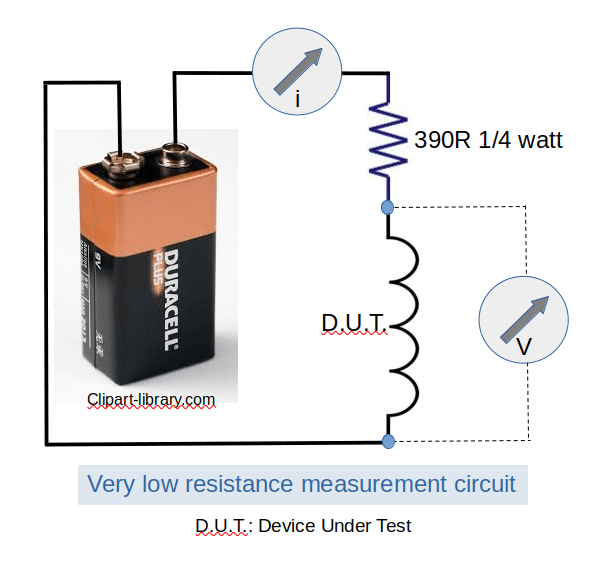
Since we will be dealing with very small values it is important to measure everything with precision. The battery had an open circuit voltage of 9.49 volts which dropped to 9.13 volts under load. The 390 ohm resistor had a measured value of 386 ohms. We can then calculate the maximum current in the circuit to be 23.6 milliamps if the coil has zero resistance. The resistor would need to dissipate 215 mW so a standard junk box quarter watt component is fine. The actual current measured was 22.3 milliamps so clearly the coil has finite resistance.
Then the voltage drop across the coil was measured using the DMM’s 200mV range. It measured just 3 millivolts. So now we have all the data needed to find the resistance of the coil. Using Ohm’s Law (R=V/I), the measured resistance came out to be 0.13 ohms.
The loading coil measured so far is a 6.6 microhenry coil wound with 20 awg insulated solid copper wire on a short length of half-inch Schedule 40 PVC plumbing pipe. This is the loading coil used with the Coil Loaded End-Fed Half-Wave (CLEFHW) discussed in the last couple of posts.
I also measured a ham-made “Wolf River Coil” style of loading coil that I have used with ground-mounted quarter wave vertical antennas. It was wound with stainless steel wire on a 2-inch diameter air-core PVC pipe. This is a significantly larger coil and its measured resistance was a staggering 5 ohms!
We will be using these two coils in a comparison exercise in just a minute. But first, let’s look at how loading coils might be used in (1) a ground-mounted coil-loaded quarter-wave vertical and (2) the Ham Radio Outside the Box Coil-Loaded End-Fed Half-Wave (CLEFHW) vertical antenna.
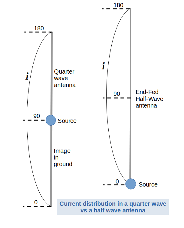
In the diagram above we can see, on the left, a classic quarter-wave vertical antenna. If it is mounted on the ground it will have an identical image in the ground and a lot of energy will be wasted cooking earthworms. Usually a set of radials is employed to reduce ground losses. If the antenna length is less than a quarter wave a loading coil may be used to electrically lengthen the antenna.
Where to place the loading coil?
A quarter wave vertical antenna will usually incorporate a loading coil at its base or at its center. Theoretically the coil could be placed at the top of the antenna but there is a gotcha. The higher up the antenna at which the coil is placed, the greater the inductance required. Greater inductance means a larger coil with increased ohmic losses. Notice also the current distribution on a quarter wave whip. The current maximum is at the base of the whip which (if what “everybody” knows is correct) will result in the greatest loss.
Why the Ham Radio Outside the Box CLEFHW does better
Now compare the End-Fed Half-Wave antenna on the right-hand side of the diagram with the quarter-wave already discussed. The current distribution pattern is the same except that instead of a quarter-wave image in the ground we now have a physical half-wave above ground. One important caveat should be acknowledged here. The CLEFHW is an electrically lengthened short whip that relies on a base-loading coil to operate. The feedpoint (or source) is at the bottom of the antenna where there is a current minimum so the ohmic losses should be minimal. Our CLEFHW loading coil is very small with very little resistance so, combined with its position at the current minimum, it should be more efficient than a larger coil at the current maximum of a quarter-wave antenna.
The lesson to be learned from electricity transmission lines.
Power companies carry their generated electricity at very high voltages. Why? If the voltage is very high the current is very low and i^2xR losses are correspondingly low. If this wasn’t done a portion of the power in the transmission lines would be lost as heat.
Now we can get down to the heart of the challenge. We have been able to measure the resistance of our loading coils, now it’s time to calculate the actual losses incurred in each case. We are going to assume our operation is QRP with a power of 5 watts. Ham Radio Outside the Box acknowledges that in some very rare cases hams actually use higher power – no really it’s true!
First up, the short whip with a big, fat loading coil at its base. The feedpoint impedance depends on proximity to ground and other factors, so let’s assume it’s a nice nominal 50 ohms. Using the formula V=(P*R)^0.5 we can calculate the voltage at the feedpoint to be 15.8 volts. From there we can deduce the current to be 316 mA (i=P/V).
Wow … that much power is lost?
We now have to make another assumption – the entire length of the loading coil is being used. Of course, if the coil is tapped part of the way along its length the numbers will be different. My coil has a resistance of 5 ohms (gasp) so the power lost, using P=i^2*R = 500 mW. Wow and double wow, that’s an enormous – no wait – insignificant 10% of our transmitted power.
So how much power is lost in the CLEFHW’s coil?
Let’s run the same math for the CLEFHW. The voltage at the feedpoint works out to be 112 volts and the current is 44.6mA. The calculated ohmic loss based on a coil resistance of 0.13 ohms works out as 5.8 milliwatts. That is around 100 times less than the base-loaded quarter-wave whip. Well bless my soul.
Alternatives?
I am quite aware of other ways to change the electrical length of an antenna. We have already briefly dealt with “top hats” (capacitance hats) in a recent post. There is also linear loading – a concept I am currently playing around with and will discuss in a future post.
This post specifically deals with the most common method by using inductive loads. Are they lossy? Well yes; but are they sufficiently lossy to be of concern? Maybe not. You form your own opinion.
Errors, Omissions and Dumb Stupidity Excepted
Please don’t accept my analysis as fact. I am an expert in the sense that X is an unknown quantity and “spurt” is a drip under pressure. I welcome any constructive criticism of this post. Please let me know your thoughts in the comments.

Help support HamRadioOutsidetheBox
No “tip-jar”, “buy me a coffee”, Patreon, or Amazon links here. I enjoy my hobby and I enjoy writing about it. If you would like to support this blog please follow/subscribe using the link at the bottom of my home page, or like, comment (links at the bottom of each post), repost or share links to my posts on social media. If you would like to email me directly you will find my email address on my QRZ.com page. Thank you!
The following copyright notice applies to all content on this blog.

This work is licensed under a Creative Commons Attribution-NonCommercial-NoDerivatives 4.0 International License.
Discover more from Ham Radio Outside the Box
Subscribe to get the latest posts sent to your email.

John I love your articles, and this one sent me off looking through your previous ones. For our field day next month, I need a 40/80m antenna that I can put up and attach to my QRP rig. I try and use a different antenna each year and last year used a Rybakov with an inverted L extension, taking it to a total length of 84′. It worked well as I had my counterpoise wire in the sea. This year I thought of using a 40m EFHW and putting a loading coil on the end for the 80m extension. Looking through your previous posts, I see you have been there and done that and have a couple of applicable formulae, so I know I’m on the right track. Thanks. Now I have to read ALL of your previous articles to see what else I have missed. At least I don’t have to take too much notice about the ones with bears in them. Keep up the good work and all the best for 2025. 73 Jim ZL1LC
LikeLike
Thanks for the great feedback Jim. Glad you enjoy reading Ham Radio Outside the Box. We are expecting heavy snow later today; I’m sure that’s not a problem down in your part of the world!
LikeLike
Interesting post again John. It explaines why my 60m endfed with coil at the center didn’t work that good. I totally forgot that an endfed is a 1/2 wave antenna. Thanks for the insight. I woke up again! Keep on thinking outside the box, I love it. 73, Bas
LikeLike
Thanks Bas!
LikeLike
The DC resistances you measured and the effective resistances at RF for your coils are not the same thing. Moreover if there is a standing wave the current into the bottom end of one of your coils may be different from the current out of the top end. So what you are calculating bears random relationship to the actual loss. I’m sure avoiding bottom loading through a coil at a high current point is a good idea, and putting less current into a lossy ground system is a good idea, but I wouldn’t want to express an opinion as to how good the ideas are.
LikeLike
Thanks for the feedback a3a05603. When you refer to “the effective resistances at RF” do you mean impedance? I did state that for a resonant antenna Z = R (in a perfect case). Maybe you can advise what I am missing here? In regard to the difference in current at the top and bottom of the coil; the coil winding length is a tiny fraction of the wavelength (i.e. ~0.02/20m). I expect the current difference to be equally small. Please expand your comment so I can fully understand your points. If I have missed something in my analysis I would really appreciate more details. BTW, a name and callsign would be helpful.
LikeLike
I tried to give my name (David Ryeburn) and call (VE7EZM) but somehow they didn’t appear. No, by resistance I mean resistance, not impedance – I’m well aware of the difference. Skin effect makes the RF resistance of your coil more than the DC resistance. And the coil is a helix, not a straight wire 20 cm long. It’s a lot longer than its “length”. Also RF may travel more slowly along the coil wire than it does in free space, making it in effect longer yet. Best way to check whether there is a current difference between what goes in at the bottom and what comes out at the top is to make an RF current meter. Take a ferrite toroid and put say ten turns of wire on it. Tie a resistor, say 50 ohms, across the winding. If you pass a wire through the hole you have in effect a transformer with 10:1 turns ratio or 100:1 impedance ratio. Then across the resistor put a diode in series with a high resistance dc load (perhaps 10,000 ohms) with a bypass capacitor across the load resistor and measure the DC voltage across the load resistor. You pass the wire whose current you want to check through the hole in the toroid. This will put about 0.5 ohms in series with the thing you are measuring which unless your antenna is VERY low impedance will not upset things very much. Check at both ends of the coil. I’ll bet you find a significant difference.
The same device can be used to check common mode current on transmission lines. Compare what you get when passing both wires of the transmission line through the hole (you’ll be looking at common mode current) with what you get when passing just one wire, and then again just the other wire, through the hole. Owen Duffy’s web pages will show you what to do with the three measurements to see how far down the common mode current is, compared to the differential mode current.
David VE7EZM
LikeLike
Ok David, yes you have made good technical points here before and your contributions are always welcome. What you are proposing in your latest feedback makes sense. I will have to give it more thought and when the winter weather is over I’ll maybe have to setup in the backyard and take some measurements.
LikeLike
I meant to measure the DC voltage across the 10,000 ohm resistor, not across the 50 ohm resistor.
David VE7EZM
LikeLike
There is no such thing as a bad antenna. If it makes us walk in the woods and try to contact our fellow ham buddies, it’s a great radiator. AG4P
LikeLike
Thanks Roger, that’s a good sentiment!
LikeLike