One of the biggest bugbears of portable operations in a public space when using a vertical antenna is having to lay out radials – either on the ground, or raised. I have told the story of the dancing lady before on this blog; she performed a little jig when advised to be careful of the wires on the ground. Some of the parks I frequent are quite small and busy in the summer months, so I always have to be cautious about creating a potential hazard for other park users.
Even if I find a nice quiet area along a trail, there is often limited space in which to spread my wires. Alternatively, I may be on a mission to operate with multiple rapid deployments – drop my pack, super fast setup, operate, move on. A small vertical antenna is a very convenient way of getting on the air with minimum fuss – except for the radials.
What is the function of radials?
It doesn’t matter whether the radials are on the ground or raised, they form a counterpoise – “the other half” of an antenna. The current flowing through the radial system controls the current flowing into the radiating element. An efficient set of radials allows maximum current to flow through the whole antenna system. The current flowing in the radiating element is equal to the current flowing into the radials. More current equals more signal being radiated.
We can throw a single wire on the ground and call it a counterpoise – there seems to be a magic length of 17 feet, at least that’s what we may be led to believe from reading many online accounts. Seventeen feet may be approximately a quarter wave on 20m, but it is detuned by proximity to the ground. Is it efficient? Well, it’s better than nothing. Without that wire the operator may become the counterpoise – RF gotta go somewhere.
Transceivers can’t count radials
Let’s pretend that transceivers have eyes for a minute. When the transceiver looks at a counterpoise – whether its made of wire radials, or has a callsign – all it really “sees” is a combination of Resistance, Inductance and Capacitance (RLC). Transceivers can’t count radials – you read it here first! Resistance, Inductance and Capacitance are seen as impedance. An efficient set of radials has a low impedance to RF which allows maximum current to flow. So isn’t the current flowing into the counterpoise system really the most important factor in determining its efficiency?
Hams endlessly debate about how many radials make an efficient counterpoise. Is it 4; is it 16, or maybe 128? The debate is pointless unless other factors are also considered. The correct number is just ONE – if your antenna is erected in seawater. I want to propose another number – ZERO and, in the true spirit of scientific endeavor, I have empirical evidence to support my assertion. If an assertion cannot be verified by experiment it just ain’t so.
“I would rather have questions that can’t be answered than answers that can’t be questioned.”
― Richard Feynman
Here is the experiment

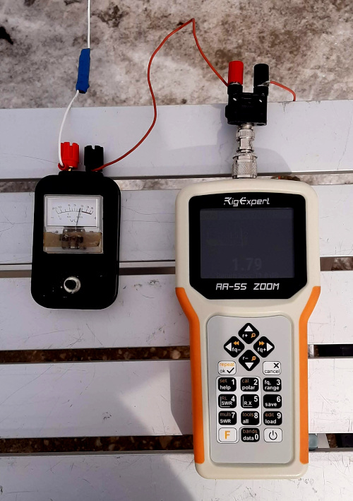
The strange blue thing in the antenna wire is a small loading coil.
Observe the higher deflection on the RF current meter after the GTU had been adjusted for maximum current in the counterpoise.
The experiment was conducted in the Ham Radio Outside the Box outdoor laboratory (my driveway). A welcome rise in temperature had melted the ice from my concrete driveway and, for once, the Sun was shining. I wanted to test a “de minimis” rapid deployment antenna that would also serve to verify my assertion about counterpoise efficiency.
The initial test was conducted with my 20m emergency wire antenna (a coil-loaded 13ft wire). Instead of radial wires I used my GTU (Ground Tuning Unit).
A GTU is a series connected L-C device. There is a sensor circuit connected to a small analog meter for observing the current passing through the device. The GTU case is a Hammond aluminum box which is electrically connected to the ground side of the GTU. The input to the GTU is a short wire connected to the shield of the coax at the antenna end.
To monitor the current in the radiating element an RF current meter was inserted into the radiator wire. The current meter is basically a GTU without the tuned circuit.
The GTU was placed directly on the concrete driveway; its aluminum box forming a capacitive connection to ground. It would have been more effective to perform the experiment on grass, but my lawn is still buried under a miniature glacier formed by another dreadful winter that isn’t over yet.
The 20m emergency antenna is nominally resonant when a counterpoise is attached so no further tuning was required. The absence of radials required the GTU to do the job of maximizing the current flow on the ground side of the antenna.
At the start of the experiment there was a small current flowing to ground. A similarly small current was observed flowing into the radiator wire (see images). The antenna analyzer recorded an SWR of 13:1.
As the GTU was tuned the ground current increased. It was observed that the current in the radiator also increased. Neither meter was capable of measuring the value of current, so the readings simply represented the relative flow of currents in the counterpoise and radiator. As the ground current peaked the antenna analyzer showed a much improved 1.79:1 SWR.
Quod Erat Demonstrandum?
So did that little semi-scientific experiment prove the point? Well kinda sorta. It established a correlation between ground side current and radiator current. But would it QSO? No, definitely not; it’s just a dumb collection of wire and electronic components – I make the QSOs eh?
Next step – hook up a radio
This is the bit where I boldy went on to risk a radio in pursuance of scientific inquiry. First, the antenna was replaced with my “tactical” 9.5ft whip wearing its finest top hat. The whip was mounted on a small tripod out on the driveway. Even with a googol (10e100) of radials this antenna would not be resonant on the 20m band. That called for deployment of my QROp L-match tuner. The radio called into service for the experiment was my old Yaesu FT-897 set for a blistering 20 watts. Since the antenna is a compromised short vertical my QRP radios were granted liberty for the day. A little muscle was called for to ensure a decent signal could be launched up to the edge of space to pound the ionosphere.
The L-match was adjusted for resonance (X=0 @ 14.113MHz), a low SWR reading on the radio, then the GTU was adjusted to max out the ground current, which lowered the SWR reading on the radio even further. Everything was ready for launch but countdown was paused for one further refinement.
A large plate for pizza?
A GTU is usually used in combination with a capacitance plate laying on the ground. The GTU body is itself a very small capacitance plate, but maybe a larger plate would enhance the ground side current flow. A quick hunt around the Ham Radio Outside the Box HQ turned up a number of options. One of the options was an old pizza pan. It worked – i.e. it raised the ground current a little, but I really couldn’t see carrying a disgusting retired old pizza pan around as part of my portable ops kit. A little further searching resulted in a small piece of what looked like chicken wire. It looked much nicer and it worked even better than the pizza pan.

The final setup – will it QSO?

Do I have to say it again? I make the QSOs not the dumb bits of wire. Well, could I make some contacts with this ZERO radial short vertical antenna system? Here is a picture of the setup.
Once again, a concrete driveway is not the best test of a GTU-based zero radial counterpoise system. The glacial layer of frozen, compressed snow on my lawn may not melt for another few weeks so one has to just make do with whatever nature allows.
I scanned the bands seeking somebody calling CQ and found a station in Connecticut doing a POTA activation. Grabbing my CWMorse paddle key I threw out my callsign and waited to hear if he heard me. Connecticut might be a little close to my QTH in southern Ontario for a vertical antenna with low angle radiation. Anyway, he heard me and sent me a 539 report. I responded with a 579. Contact was made.
A popular mantra among hams is “one is none and two is one” so I figured another contact would hammer a nail in it and seal the proof.
A little more search and pounce revealed another POTA activator in Virginia. Still quite close but my contact there earned my modest setup a 579 report.
Both those contacts were on 20m and I wondered whether another band would also work. I tuned up on 15m but the band was frantically busy with high speed CW traffic and I didn’t want to slow anybody down with my low power into an experimental antenna so I pulled the plug.
So there we have it. A very simple, rapid deployment field portable vertical antenna with zero radials. Now how am I going to make the ladies dance?

Help support HamRadioOutsidetheBox
No “tip-jar”, “buy me a coffee”, Patreon, or Amazon links here. I enjoy my hobby and I enjoy writing about it. If you would like to support this blog please follow/subscribe using the link at the bottom of my home page, or like, comment (links at the bottom of each post), repost or share links to my posts on social media. If you would like to email me directly you will find my email address on my QRZ.com page. Thank you!
The following copyright notice applies to all content on this blog.

This work is licensed under a Creative Commons Attribution-NonCommercial-NoDerivatives 4.0 International License.
Discover more from Ham Radio Outside the Box
Subscribe to get the latest posts sent to your email.

Great article…. 73, KJ5LSO
LikeLike