What in Heaven’s name is a “CFHW”?
A CFHW is a Center-Fed Half-Wave antenna. You may know it better as a dipole and it is indeed a highly efficient simple wire antenna. I can’t claim originality for the term “CFHW”; it started as a joke on one of the forums I follow. Following the trend of using abbreviations it falls in nicely with “EFHW” and “EFRW”. Now that we have shared the joke let’s revert to using its proper name: dipole.
No lossy impedance transformer is required for a dipole. It’s just two quarter wavelengths of wire held together in the middle by a center insulator. And a feedline; a very long feedline. I carry one in my field kit as an emergency standby but I hope I will never have to use it. An obvious question to ask is “why?”. And another question you might ask is why do I prefer an End-Fed Half-Wave that, according to several sources, is the work of the Devil?
Born to be wiled
An End-Fed Half-Wave antenna is, as its name suggests, a half-wavelength long. But so is a dipole. “An EFHW is only a half wavelength long at one frequency” critics say. Correct, but so is a dipole. A dipole is only good for one band or maybe even only one part of one band, but an EFHW can be used on every even harmonic, making it a multiband antenna, claim the wiley marketers of such products. On the basis of this dubious claim hundreds, maybe thousands, of antennas have been sold to hams to use from 80m to 10m without any adjustment. Does convenience trump antenna physics?
Stand and Wave Rapidly

It is true that an EFHW antenna presents a low SWR at some point in every even harmonic band. So where’s the deception? First of all, the bands are not exactly harmonically related. The low SWR point may fall outside of whichever part of the band our license privileges, or our choice of mode, permits. Secondly, SWR is not an indication of the efficiency of an antenna. If an EFHW is built for 80m and uses say, a 49:1 impedance transformer wound on a type 43 toroidal core, its efficiency may vary considerably from band to band. Well-informed critics claim the efficiency of a high ratio impedance transformer is low enough already so nothing good will come of trying to use it on multiple bands. Perhaps we may as well grab a small flag in each hand and SWR (Stand and Wave Rapidly) instead.
Bonkers or what?
The radiation pattern of a half-wave wire is the same irrespective of where it is fed.
The difference between an EFHW and a dipole arises simply from where it is fed. A dipole is fed at its center where the natural impedance is low enough to keep our transceiver’s PA finals from reacting exothermically. An EFHW is fed at one end where the magnitude of the impedance exceeds the imperial height measurement of Toronto’s CN Tower (the CN Tower in downtown Toronto stands at 1815ft, 553m high). So a dipole can be fed without any impedance transformation whereas an EFHW requires a high ratio impedance transformer. It is beginning to look like it would be absolutely bonkers to choose an EFHW over a dipole, so wassup?
The long and winding road to the feedpoint
A clue to the problem was given in the first paragraph of this post. A dipole requires a very long feedline. Long feedlines have two shortcomings: they carry the risk of losses, and the biggie … they are gravitationally challenged, i.e. they are heavy. Want to use a lighter coax feeder? More loss. Want low loss? More weight. Pedestrian portable operators, like myself, need to avoid carrying heavy coax cables. A dipole requires three supports; one at each end plus a third in the center.
Is the center support really necessary? No, but without it the dipole will sag in the middle and, if there is sufficient sag, that will transform a flat top into a “V” and the radiation pattern will change quite dramatically. A “V” orientation results in most of the signal going straight up and disappearing into space on the higher bands. This can be avoided by using an “Inverted-V” design.
Are end supports really necessary? No, the antenna can be erected as an inverted-V, but in order to keep the recommended wide angle between the arms of the dipole a lot of real estate is needed. Don’t worry, the park rangers and other park users will understand.

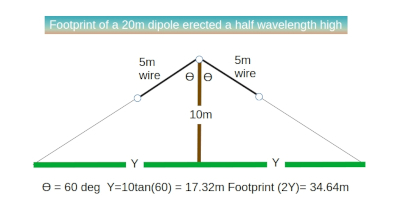
Example:
20m dipole erected with its apex at 10m high and angle of 120 degrees between its arms requires a ground space of 34.64m (~114ft).
Softly, softly catchee monkey
When amateur radio operators venture out into the field we often have to subjugate antenna physics behind expedience and courtesy towards other park users. If you know of a location where you can erect a large footprint antenna without attracting the ire of park rangers (known as “park wardens” in Canada) you are lucky. Here in Southern Ontario there is very little “Crown Land” (BLM in the U.S.) where we can erect large antennas. Our governments have sucked up all the Crown Land and turned into highly regulated national or provincial parks. Putting up an efficient antenna without drawing a lot of attention requires a degree of stealth and ingenuity. “Big” can be seen as “dangerous, suspicious”.
O.K. Dipoles are out, but why End-Feds?
Going back to why the critics dislike End-Fed Half-Wave antennas so intensely, we can see that their disapproval centers on the following:
- EFHW antennas are only a half-wave on one frequency and, grudgingly, maybe its second harmonic (on some bands)
- Operating an EFHW on multiple bands is a deceptive marketing ploy; low SWR does not imply high efficiency. This is disputed by some due to a misunderstanding of SWR but Joeri ON6URE, “the RF Guru”, states categorically that: “Mismatch efficiency ≠ antenna efficiency“
- Broadband, high ratio transformers are lossy.
So, if those factors are eliminated, what’s not to like about a half-wave wire for a field antenna? An end-fed antenna can be connected to the transceiver using a very low-loss short coax. That makes it very convenient for field portable operations. The coax can be a low-loss type such as RG-316 which is very lightweight, as long as we are not running too much power.
And now, the end is near
And so I face the final paragraph
My friend, I’ll say it clear
I’ll state my case, of which I’m certain …
Cut a wire that is a half wavelength long on the primary band of interest, for example 40m. It will also be usable on its second harmonic (20m) without inviting fire and brimstone from the critics. Now feed the wire at one end in one of two ways.
- Using an AA5TB parallel L-C coupler (link: A 20-minute QRP End-Fed Half-Wave antenna coupler)
- Using a tunable L-match (link: A highly efficient multiband QRP L-match builder project)
One last thought
The parallel L-C coupler championed by AA5TB comprises an inductor with two windings. The secondary winding is in parallel with a variable capacitor for tuning. Both the primary and secondary are wound on a powdered iron toroidal core with a turns ratio of 7:1. Sounds familiar? That’s an impedance ratio of 49:1. Is that more efficient than a 49:1 impedance transformer wound on a type 43 ferrite core? Anyone care to comment?

Help support HamRadioOutsidetheBox
No “tip-jar”, “buy me a coffee”, Patreon, or Amazon links here. I enjoy my hobby and I enjoy writing about it. If you would like to support this blog please follow/subscribe using the link at the bottom of my home page, or like, comment (links at the bottom of each post), repost or share links to my posts on social media. If you would like to email me directly you will find my email address on my QRZ.com page. Thank you!
The following copyright notice applies to all content on this blog.

This work is licensed under a Creative Commons Attribution-NonCommercial-NoDerivatives 4.0 International License.
Discover more from Ham Radio Outside the Box
Subscribe to get the latest posts sent to your email.

As always, a very good article.
AA5TB’s link is not work.
TNX 73 Atila, TA1DX
LikeLike
Thanks Atila. The link is fixed now.
LikeLiked by 1 person
Morning, John
I used dipoles for my outdoor adventures for 20 years. Then I became active on the internet and learned about the EFHW. I wouldn’t use anything else now. No tuner, no feedline, no radials. It’s made things so much simpler. To me the benefits outweigh any drawbacks.
I tune my 40m (20 mtr long) EFHW to be resonant on 20m. That way it’s a little out on 40 and a little out on 15/10 insted of getting progressively worse as I go up in frequency.
I also found the resonant points on my wire for 30 and 17 meters. That way I can just wind the wire out to those points and have one wire cover 6 bands.
The ends of my antenna are only picnic table high and the middle is at about 5 meters. I don’t do any of the xxOTA stuff, so there’s no pressure to get contacts. That means no worries if all I get is the fresh air. Practical beats efficient any day!
LikeLiked by 1 person
That’s a good philosophy. Tuning your 40m EFHW for 20m is a good idea but I would still be cautious about the radiation pattern on the higher bands.
LikeLike
Hello John,
ka7umr here,
Over the years I’ve tried all of these antennas, and they all “work”. I purchased a 19′ vertical with a 6:1 unun at the base. It worked and I used it for a year or so. I read an article about a vertical dipole. It consisted of a vertical element and a horizontal one with an auto tuner at the base. I thought, how could this be of any use. So, I removed the unun, purchased 4, 5.5′ Buddie Pole extending whips for the horizontal portion. Mounted the LDG remote tuner at the base. The swr must be as high as the Toronto Tower, but pskreporter shows my 50w ft8 signal received from Asia to Africa. Now, received is one thing, QSO another, but I don’t think I’ll mess with success. Atleast not for a while. Bob.
LikeLike
Hi Bob; it’s a great idea to experiment, even if the experiments do not give the result you were looking for. Failed experiments are really a successful learning experience. And if your signal is still getting heard maybe it’s not a failure anyway.
LikeLike
Hi John –
Great article 🙂
I’m of a mind that sense of humor is prerequisite to sensible.
To wit, a few experimental acronyms for antennae both tried and true and within the realm of theory include –
UDMV. The Upside Down Messy Vee (and it’s fan version) continues to be a favorite. After a few months of claustrophobia, limited to a tribander, I hoisted the pm’d wire set back up. Within 10 minutes of coaxing the cats fo allow me on the chair, my first QSL was Neurmayer Station. Cat heard me say something like ‘I missed you too old friend,’ and suspected he was not the audience. Cats are like that.
The UDMV gets it’s name due to small yards, trees, someone built the house in the way of my antenna, etc. It allows for all the imperfections that the MPH A (More Precise Ham Afficionado) would warn us from –
the angle is a bit less than 60 deg; – one leg lands higher than the other; – the higher leg takes a 25 deg turn mid wire down between homes, under a 6ft wood fence, and is tied to a chain link at the front yard. – the lower leg makes a sharp turn on a branch near the center, then heads to a fence spot a bit closer than the other – in relation to the ground (not that ground, the other ground), it’s about 37 degrees sideways, slanting from S to N. – all of the above can be explained in one word when you’re speaking to someone from Texas: Cadiwhompus.
Messy. But, during a thunderstorm, when the rope tie is pulled and it drops to the ground with one side draped o’er the deck, I can still work the EU from MN. (need another province? Albeit small? I think we get most of our electricity from y’all. Pull the plug – we’ll smile and shrug when the US’ credit cards all stop working. Symbiotic relationships are essential parts of a good breakfast.
POQW (Pair Of Quarter Wave)- this is the dual-end fed version of the CFHW. The two are identical. This might be more acceptable packaging of the concept, admittedly due to the fact that both wires are fed at the end.
OCFV (Off Center Fed Vertical) – I have balance issues. With this antenna too. Keeps falling over. This is not to be confused with Burt Fischel’s OCFFlagpole at W9VOB (he is the sole recipient of the WAGD – worked all garage doors – certificate I had made for him)
T (T) – Even looks like a T. It’s shaped like… well, you know… Works best with a Birdhouse. Who knew that birds could operate the coil/cap and switch that shorted the twin line together to get an 80M wire a chance to do 160M. Is it a vertical with a capacitance hat? Is it a fed horizontal? Why does it have trouble loading after wire on the ground have loaded the lawnmower… all experimental.
ZWHN – I have to agree, a Zep Without Hydrogen Nearby, has advantages over the original.
Enjoy your articles! Looking forward to the next
73
Ken
w0yre
LikeLike
Thanks Ken. I like your humor too!
LikeLike