There has only been one light snowfall in southern Ontario so far this season – just a few centimeters that melted away within a couple of days. In anticipation of upcoming heavier snowfalls and a semi-permanent white blanket that will last until spring, I bravely shrugged off the chilly outside air and set up my Ham Radio Outside the Box version of the POTA PERformer antenna out in the backyard to experiment with radial lengths.
The cunningly repaired broken shortened whip with a capacitive top hat, to compensate for its inductive reactance on the 20m band, sat atop my custom spike mount that, despite falling temperatures, could still be pushed into the ground about 25cm (10 inches). Two radials were attached each of which sloped down to a fiberglass stake about a foot (30cm) above ground. The radials are approximately 5m (17ft) long for the 20m band with links to shorten the wires for the 17m and 15m bands.
Now, to find a shortcut
The objective for the day’s tests was to investigate whether compromises could be made in the radial lengths. Why? Later in the winter, when the snow lies deep and crisp and even, it can become a real chore to wade through accumulations of the infernal white stuff to adjust the radial lengths for band changes. I have adopted 2mm banana plugs for the links – a great idea in the summer, but maybe I neglected to consider what will happen when even a few snow flakes freeze on those tiny connectors in the winter!
So, how to minimize pedestrian excursions through the challenges of winter operating conditions to accommodate band changes? The POTA PERformer is an efficient antenna but it was designed in California where the climate is just a little milder than in Ontario. Should I go back to using a random wire antenna – like the Rybakov – until spring comes around again?
I could perhaps use “fan radials” i.e. separate radials for each band. That would probably work but setting them up might still involve wading through deep snow. In the past I have used ground radials laid on the snow – a multiband arrangement that requires no adjustment for band changes, but is less efficient.
Back to the backyard tests; what did I find out?
- First, my approximately 16.5ft (~5m) raised radial wires provided an acceptable SWR (less than 2:1) on 20m and 17m (with the whip length shortened for 17m).
- Second, the same wires – with the links adjusted for 15m and the whip shortened again – gave an acceptable SWR on 15m, 12m and 10m.
So, is this a result? Maybe not. There is a potential for lost efficiency when the radiating element is shorter than the counterpoise. Let me explain.
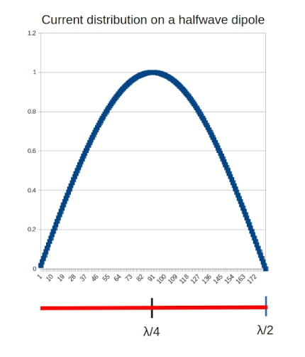
Let’s assume we are using a field portable version of the POTA PERformer in which the feedpoint remains quite close to the ground – maybe 1 to 1.5 meters. The two radial wires slope away from the feedpoint to an end point even lower to the ground. Now, if we examine the current distribution on a halfwave dipole, we can see that the maximum current, and therefore the point at which maximum RF is radiated, is located in the center of the dipole.

We would like the high current point to lie within the radiating element, not the counterpoise. For the purposes of this discussion we are going to refer to the two radial wires as “the counterpoise”.
Going back to my backyard tests, I found that:
- a 20m counterpoise “worked” on the 17m band.
- a 15m counterpoise also “worked” on the 12m and 10m bands.
In each of these cases the radiating element was shorter than the counterpoise.
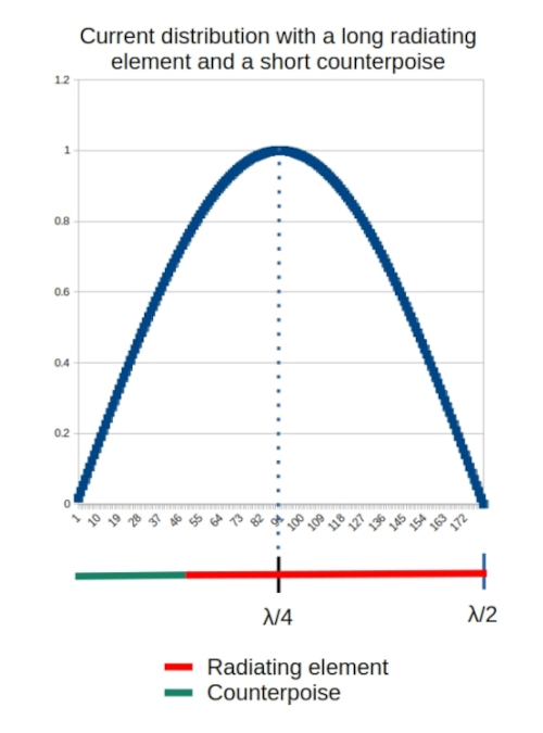
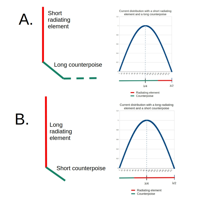
Referring to the accompanying diagrams we can see that the high current point, in each case, lies within the counterpoise.
Does this finding matter?
Changing the radiating element versus counterpoise balance creates an antenna that looks very much like an Off Center Fed Dipole (OCFD).
If an OCFD is mounted high enough above ground it doesn’t matter at all although two things need to be considered here:
- Changing the radiating element versus counterpoise lengths changes the impedance at the feedpoint.
- The overall length of the dipole might change unexpectedly. This can be seen with Greg KJ6ER’s Challenger antenna which is a vertical OCFD halfwave dipole that is shortened by laying part of the counterpoise wire on the ground.
A relatively small change in the ratio between the radiating element versus counterpoise lengths changes the feedpoint impedance, but this can be compensated by adjusting the whip length to still obtain a usable SWR.
However, we cannot compensate for the proximity to ground of the counterpoise in the POTA PERformer. If the current maximum occurs at the feedpoint (1 to 1.5 meters above ground) very little power is lost. But, if the current maximum occurs below the feedpoint we are going to keep the earthworms warm in winter.
Not the best plan
So we can conclude that using a 20m counterpoise on 17m risks losing some of our RF energy to the ground. The same applies for using a 15m counterpoise on 12m and 10m. The following diagram summarizes this.
The way forward
“Fan radials” may still be a solution but they require some careful experimentation. There is interaction between the wires for each band due to mutual capacitance. This is compounded when multiple bands are involved. To make matters worse, when used out in the Big Blue Sky Shack where the wind doth blow through the wires and changes the interaction, who knows what wild swings in SWR may occur? The radio I have dubbed my “very clever poodle” (QMX: see last post) will not take kindly to that.
A final thought
I have watched several videos in which a very short whip is mounted on a picnic table and used with a single long counterpoise wire draped down to and across the ground. Sometimes the “Magic (Tune) Button” assists in finding an SWR that keeps the radio smiling. Contacts get made, so what’s the problem? I hope the above discussion answers that question.

Help support HamRadioOutsidetheBox
No “tip-jar”, “buy me a coffee”, Patreon, or Amazon links here. I enjoy my hobby and I enjoy writing about it. If you would like to support this blog please follow/subscribe using the link at the bottom of my home page, or like, comment (links at the bottom of each post), repost or share links to my posts on social media. If you would like to email me directly you will find my email address on my QRZ.com page. Thank you!
The following copyright notice applies to all content on this blog.

This work is licensed under a Creative Commons Attribution-NonCommercial-NoDerivatives 4.0 International License.
Discover more from Ham Radio Outside the Box
Subscribe to get the latest posts sent to your email.

Hello I don’t understand all english language…. For me in POTA or expedition, i prefer for a vertical put 4 short radials on the ground, ( about 5m in X position. ) A long radial is not good for the direction of waves. I prefer a vertical 1/4 wave on ground ( with 10 watts ) than a a short vertical on the mobile ( with 50 watts )77 years old , i like chasser POTA I like activation , but I don’t understand what I have to make for activate ( adif for log, position with GPS or Photo !!!!!) A good week end for you Francky -ON5SE , ON5QRP before
LikeLike
Thanks for the comment Francky. I have also used just 4 radials with a vertical whip when operating portable. It is not an efficient arrangement but it does get contacts. POTA activations are quite simple; you only have to log the hunter’s callsign and the time of the contact. Most activators also log the hunter’s QTH and sometimes the signal report too. No GPS coordinates or photos are needed. You can upload an adif or enter your contacts manually on the POTA website. Good luck and 73 de John VA3KOT.
LikeLike
Tkank you for all informations John – I like to go in WFF outdoor, in CW only on my side.
Good week my friend for you and familly – Fan
LikeLike
hi John-
[background- I use only resonant antennas in the field. Homebrew rigs with no SWR bridge/tuner needed.]
I’d reworked my POTA antenna a couple months ago- it lowered the feedpoint from 12 feet to 6 feet. It made deploying the antenna a good deal easier. The Hustler whip at the top was replaced with a 17-foot whip. I was a little surprised to find that 20M resonance was on the high side- at 14150 kHz. It suggests that the two existing radials were a bit short. In effect- a slight OCF effect- raising the feedpoint impedance.
Dropping the feedpoint to 6 feet meant that the radials were closer to ‘horizontal’ instead of drooped ~45 degrees down. This lowers the antenna’s characteristic impedance. The slight OCF effect worked to my advantage.
Rather than reworking the radials to add length, there was one easy step to lower the resonant frequency. Resonance dropped nicely to 14040 kHz when I lowered the radial-ends to 6 inches above ground. Capacitive end-effect. I was concerned that this would adversely affect the antenna efficiency. The large majority of the radial length is still well above ground, though, and the modeling showed it made little difference.
72/73- Dave, K1SWL
LikeLike
Always interesting to share ideas with you Dave. I had a similar experience with my “Long Tall Sally” antenna (old post on this blog). A very long radiator with very short radials. The length and angle of the two short radials affected tuning. Even a small change in length had an impact. In that extreme case the feedpoint impedance changed so much I had to match it with a 4:1 unun.
LikeLike
That makes sense. You ended up with an OCF vertical. There was an OCF vertical a while back that added a second -and shorter-antenna as a Director element. It made it a 2-element Yagi. If you had plenty of space for antennas, you could probably walk the Director around to make it steerable. In my case, I’d probably aim it at Europe and leave it at that.
I recently put up an inverted-Y for 80M. It’s supported by a 60-foot tree. The trick there is that the vertical element is linear-loaded. It’s 300-ohm ladderline- shorted at the top and one wire open at the bottom. It’s resonant at 3540 kHz with a 44-foot height. It’s more narrow-band., though. ‘No Free Lunch’.
72/73- Dave, K1SWL
LikeLike
This superb treatise of simplified excellence will be studied with the consideration of how long radials really need to be. In your case elevated.
A survey of several vertical manufacturers suggest a ground layed radial of something like 12.5 ft is acceptable for 40-10. It would Be interesting for you to apply the same max current logic to ground mounted for length determination.
Another radial Logic is overlapping them much like spokes in a bike wheel. Increased Solidity ?
I also read about the effect of having coax running over or under radials with and without a choke at the antenna feed port.
So much to learn about in my vintage age….and tomorror my W3EDP jr tests writhing the rig expert 230.
Bruce Aa1ar
Ps you cananadian and British chaps are so much more professional compared to the USA common dogs…😝😝😝😝
LikeLike
I have used a guideline of laying ground radials that are shortened by 20%, but that only applies to a single radial wire which is not very efficient. For field portable operations 4x13ft radials are a satisfactory compromise between efficiency and expedience. For a permanent antenna at least 16 radials are needed and some sources I have read suggest the length is less important than the number of radials. But the better solution is to raise the feedpoint at least 3 feet above ground – and preferably higher. Then as few as 2 radials can be as efficient as 16 radials on the ground.
LikeLike