Following on from the previous post, there seems to be some interest in how the Simple, Low Profile, Multiband POTA antenna was actually built. Although the antenna is described as “simple”, that term relates more to how it is deployed and its appearance than its actual construction.
The construction does not involve any special tools or techniques, but it does involve some care to transform a photographer’s lighting tripod into a ham radio antenna. This is especially true since only the top two of the three vertical tube sections of the tripod are used as part of the antenna radiating element. The base tube section, to which the legs are attached, is only used as a support structure for the rest of the antenna. Thus the problem emerges of how to electrically isolate the top two tube sections from the bottom tube.
Where can you purchase such a tripod?
I was able to buy one from my local Habitat for Humanity charity store but a very similar product is available from Amazon. Simply search your local Amazon online store for “Amazon Basics Aluminum Light Photography Tripod Stand with Case”. It is a very inexpensive product – even here in Canada!
Where can you purchase the whip?
The whip can be purchased at hfportable.com (“Home of the Buddipole”). Search for the “Long Telescopic Whip”. I already owned one of these that I acquired several years ago and mine measures 9 feet 4 inches fully extended. The product on the Buddipole website describes it as being “nearly 10 feet long”. As an alternative you could use any 17ft telescoping whip extended to 9 feet. The tripod tubes form the other 4ft of the radiating element. Peter G3OJV advises against using a longer radiating element. Apparently 13 feet is the magic length for this antenna.
Adhesive copper tape
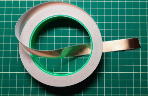
After completing the basic build I realized adding copper tape to the contact areas would be a good idea. There is a choice of copper tapes available from your friendly mom-and-pop Amazon store. I purchased 15mm tape which came on a 20m roll (20 meters, that’s interesting; I wonder what else I could use it for?)
Conductive grease
The tripod tubes nest inside one another allowing the tripod to be collapsed for transport and storage. This means contact will be made and broken at every deployment. Therefore I recommend conductive grease to lubricate, prevent oxidation and assist high conductivity where the tubes connect to each other.
Challenge #1: Joining the lower radiating tube to the bottom support tube
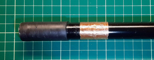
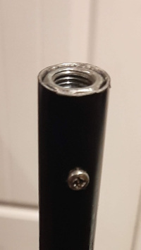
There are three tubes in the tripod. The top two tubes, along with the whip, form the radiating element. They must be electrically isolated from the bottom tube. Although the tubes are coated with a thin layer of black paint, continuous use may create scratches leading to unwanted conductivity. A short length of shrink tubing over the bottom of the second tube fixed that issue. Note in the picture the copper adhesive tape applied over a bare section of the tube (after paint was removed with a Dremel tool). This is where the feedpoint is connected.
Coax is attached by means of 3/8×24 CB mirror mount fixed onto the copper tape feedpoint area. This was described in the previous post. The mirror mount is fastened with two bolts with wing nuts so that it can be moved when the antenna is taken down.
There is a possibility that a very small capacitive coupling between the overlapping sections of tube will occur although no adverse effects of any such coupling have been observed.
The lower tube section is electrically isolated from the legs by means of plastic fixtures, so there is no ground connection. The lower tube section is therefore just electrically floating.
If any RF is getting across the junction of the two lower tubes due to capacitive coupling it is likely to be so small as to be inconsequential.
Challenge #2: A good electrical connection between the upper tubes
Isolating the top two sections of tube from the base section was relatively straightforward. Now the problem of how to ensure a very good electrical connection between the top two sections had to be dealt with.
The tubes are concentric, but are a loose fit to enable the intended light fixtures on top of the tripod to be raised and lowered easily. But the loose fit became a problem when the need arose to electrically connect two sections. Not just connect, but ensure a very low resistance connection was made. It would be highly undesirable if the connection were intermittent or had a high resistance. “High resistance” in this context could be as little as an ohm or two since the RF current this close to the feedpoint is quite high.
So here is how the problem was tackled. As can be seen in the accompanying image, two broad slits were sawn in the top end of the center tube section. The plastic clamps that secure tube sections together compress these slits.
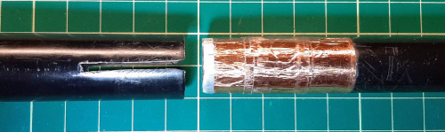
Now it was only necessary to use layers of copper tape to create a slight bulge at the bottom end of the top section of tube, where it mates with the center section. When the antenna is erected the copper tape bulge in the top tube engages with the compressed slits in the center tube and form a secure electrical connection.
Challenge 3: Connecting the whip
The whip is attached to the top end of the top tube of the tripod. It would have been very simple to use a CB mirror mount, but I wanted the entire assembly to appear as one continuous length of tube.
To achieve this it was necessary to fix a 3/8×24 coupling nut inside the top end of the top tripod tube. I guess I got lucky here because one of the coupling nuts in my junque drawer turned out to be a nice snug fit inside the tube. But a snug fit isn’t good enough for an electrical connection so a tiny hole was drilled through the tube and coupling nut. A small nut and bolt was then added to ensure a tight fitting. For good measure, the outside surface of the coupling nut was coated with conductive grease to reduce the electrical resistance and prevent corrosion during use outdoors in the Big Blue Sky Shack.
I hope this post will encourage others to build their own version. As was shown in the last post, the antenna does a creditable job and is so easy to transport to a park (or mountaintop) and super fast to set up. I am happy to respond to any further inquiries; just leave a comment below or send me an email (qrz.com has my correct email address).

Help support HamRadioOutsidetheBox
No “tip-jar”, “buy me a coffee”, Patreon, or Amazon links here. I enjoy my hobby and I enjoy writing about it. If you would like to support this blog please follow/subscribe using the link at the bottom of my home page, or like, comment (links at the bottom of each post), repost or share links to my posts on social media. If you would like to email me directly you will find my email address on my QRZ.com page. Thank you!
The following copyright notice applies to all content on this blog.

This work is licensed under a Creative Commons Attribution-NonCommercial-NoDerivatives 4.0 International License.
Discover more from Ham Radio Outside the Box
Subscribe to get the latest posts sent to your email.

Just a note on copper tape. I bought mine from the gardening section of a dollar store. The adhesive wasn’t conductive. Tapes sold for electronics purposes usually have conductive adhesive. It isn’t a problem if you check before using it, since you can remove the adhesive from most of the contact area before applying it.
LikeLike
Thanks for warning! Mine is from Amazon and the adhesive is conductive. Gardeners use copper tape to keep slugs off plant pots so the adhesive doesn’t have to be conductive.
LikeLike