A fierce debate rages on one of the online forums I read. Is an End-Fed Half-Wave (EFHW) truly a multiband antenna? By “multiband” I mean resonant on even harmonics without a tuner. The most vocal posters in that forum keenly disparage these popular antennas despite their popularity.
Resonant on every band, earn DXCC in a single day!
It is possible to blow away a lot of money buying a commercial version of the EFHW for which vendors sometimes paint glamorous images of their product’s features and capabilities. That is one of the reasons the curmudgeonly forum folk like to open fire with their high caliber keyboard ammunition. They take shots at the popular broadband 49:1 impedance transformer, but reserve their most powerful ordnance for any claim of “multiband” performance.
Thousands of hams must be wrong
Strangely, many hams have used an EFHW with great success. It is a particularly popular antenna among SOTA and POTA activators. It only requires a single support structure; Canada has 300 billion environmentally friendly arboreal support structures available. An EFHW can be fed close to the ground because the feedpoint is a high voltage, low current point. A very short coax feedline can be used, or no feedline at all in fact. Some QRP operators don’t use any kind of counterpoise although a wire stub 0.05 wavelengths long is recommended – especially where no coax feedline is used.
Ham Radio Outside the Box decided to investigate whether an EFHW antenna is truly a tunerless multiband antenna. We were surprised by the results. For this study a 75/80 band EFHW was used. Can such an antenna operate on all the HF bands up to 30MHz?
Baby its cold outside
The current weather at my home QTH in the lee of mighty Lake Huron is typical for a harsh winter’s day in the High Arctic. But the High Arctic is 2000 miles further north so, even though those of us who make our homes here routinely stir our coffee with our thumbs (see note below), it’s a bit rough outside for erecting antennas. Being a coward when it comes to the cold I decided to perform this analysis by plugging numbers into a spreadsheet instead.
Note: A reference to the folk song “The Frozen Logger”
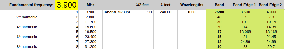
Let’s start in the band basement at 3500KHz:

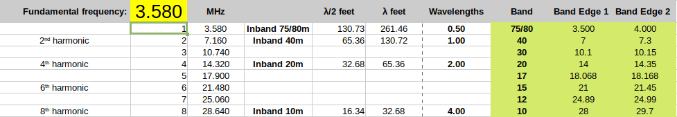
Yes! It appears that an EFHW cut for the bottom of the band may be resonant on each of the even harmonics. As we move up the band to 3580KHz we lose the 6th harmonic on the 15m band.
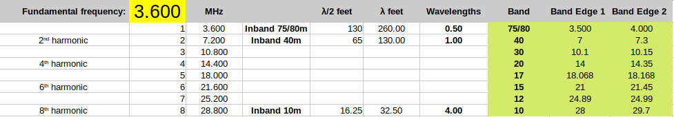
Turning up the dial a little further to 3600KHz we now lose the 4th harmonic on the 20m band.
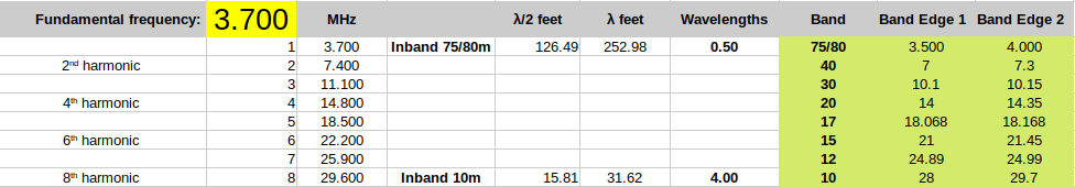
The 2nd harmonic on the 40m band disappears when we move up to 3700KHz
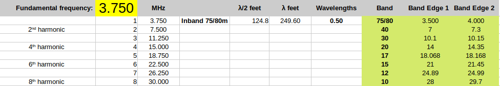
As we enter the phone portion of the band at 3750KHz we also lose the 8th harmonic. Now our antenna has become a monobander.
Let’s zip up to 3850KHz where (according to my ancient band plan chart) US General license holders get SSB access. Same result. In fact nothing changes all the way to the dizzying heights at the top of the band.


It seems that the best harmonic performance occurs at the bottom of the 75/80m band (in Canada we do not distinguish between 75m and 80m; everything from 3500 up to 4000 is referred to as 80m).
The HF bands have widely different bandwidths as seen below in this chart:
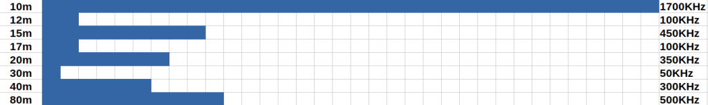
The band width chart suggests that we have very little expectation of finding a harmonic relationship between a wide band such as 75/80m and other bands – especially the WARC bands. Surprisingly, despite being the widest band, even 10m does not align too well.
Lets present the same chart from a different viewpoint using harmonic relationships.
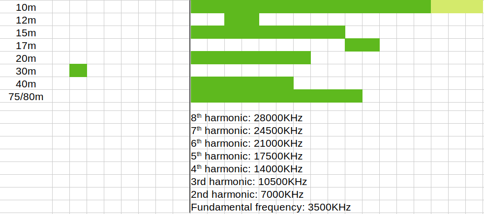
In the chart above the bold vertical black line marks the origin frequency at each harmonic. Each HF band is then presented relative to the harmonic frequency. We can see that the 30m band is way out in left field while the 12m band is a near miss. In fact, if we cut our wire for a half-wave at 3560KHz something magic happens:
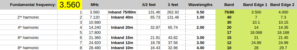
Now surprisingly we find a harmonic relationship on the 12m band, which is an odd (the 7th) harmonic.
Things to note:
- An EFHW antenna is only an exact half-wave on one frequency. However, adjacent frequencies may be close enough to still present an acceptable SWR to your radio.
- Conditions along an antenna repeat every half wavelength. It is therefore reasonable to expect resonance (or near resonance) at harmonic frequencies when those frequencies coincide with the higher bands.
- Harmonic relationships only make it more likely to obtain resonance on the higher bands; they do not guarantee it. Other factors also come into effect – for example, “broadband” 49:1 transformers.
What about those “lossy” 49:1 impedance transformers?
Ham Radio Outside the Box countered the myth about “lossy” inductors in our last post. Loss in an RF transformer has two sources.
- i^2*R heat loss. However, if the current “i” is very low – as it is indeed at the feedpoint of an EFHW antenna – these losses should be very small
- Magnetic coupling efficiency. This has so many variables that it is difficult to give a firm opinion.
- Choosing the right ferrite mix for the frequency on which you plan to operate is probably significant. One ferrite mix may be optimized for the low bands while another is optimized for the high bands. If a toroid is chosen for, say, the low bands it may be less efficient on the higher bands. This alone makes multiband operation questionable.
- How many ferrite cores should be used to avoid overheating? If a core gets above its “Curie temperature” its performance changes dramatically.
- Is the transformer inside a sealed enclosure? If so it may overheat more quickly.
- What size toroid is right for the RF power at which you will be operating?
- What winding method is used for the transformer? Close wound or turns spread around the core? Autotransformer or separate primary and secondary?
What about a counterpoise?
Is a counterpoise necessary for an EFHW antenna? This is a “pistols at dawn” type of argument. The feedpoint of an EFHW has a very high impedance so the current is very small. Many QRP operators don’t use a counterpoise at all, but I have found it does have a small impact. If a coax is used then the outer surface of the braid is usually adequate for dissipating common mode current. Alternatively, a short counterpoise wire of one-twentieth of a wavelength at the lowest frequency of operation is recommended.
Does adding a short counterpoise turn an End-Fed Half-Wave antenna into a highly unbalanced Off-Center Fed Dipole (OCFD). Theoretically it does, but is that significant? Maybe not.
“1:1 SWR – perfect”!
It is often forgotten that the SWR at the rig end of a coax is usually not the same as the SWR at the antenna feedpoint. My RigExpert antenna analyzer allows me to null out any feedline by recalibrating at the rig end. And, finally, pressing the magic “Tune” button on your radio and getting a 1:1 match does not mean the antenna is just perfect. The function of a tuner is to provide a matching network between the input and output impedances, sometimes over quite a wide range. A 1:1 match at the radio might mean as much as a 10:1 SWR at the antenna!
Don’t worry, be happy!
Suppose we are more interested in making contacts then researching for a doctoral thesis on antenna physics. I actually did graduate with a bachelor’s degree in physics some 50 years ago and retain a passionate interest in the subject. But, when I am out in the Big Blue Sky Shack with a temporary antenna calling CQ and harvesting all the return calls for my log, I follow the following advice:
The antenna you have erected works better than the one you haven’t put up because you are unsure how efficient it might be.
While it is interesting and educational to learn and understand antenna theory it shouldn’t be a distraction from actually getting on the air. I like to think of the Special Operations Executive agents working behind enemy lines during the Second World War. Their typical antenna was a random wire passed through a window with the end thrown in a tree. They cared more about passing radio traffic and getting off the air quickly before the enemy arrived with their radio direction finding equipment … and machine guns.
Performing this theoretical analysis has helped me understand why there are widely different opinions about End-Fed Half-Wave antennas. I hope you too will find it useful.

Help support HamRadioOutsidetheBox
No “tip-jar”, “buy me a coffee”, Patreon, or Amazon links here. I enjoy my hobby and I enjoy writing about it. If you would like to support this blog please follow/subscribe using the link at the bottom of my home page, or like, comment (links at the bottom of each post), repost or share links to my posts on social media. If you would like to email me directly you will find my email address on my QRZ.com page. Thank you!
The following copyright notice applies to all content on this blog.

This work is licensed under a Creative Commons Attribution-NonCommercial-NoDerivatives 4.0 International License.
Discover more from Ham Radio Outside the Box
Subscribe to get the latest posts sent to your email.

Hi John. My two cents worth – generally speaking, it is not necessary for an antenna to be resonant to radiate well, with some exceptions. This fact is stated in the ARRL Antenna Book. Nor does resonance guarantee a low feedpoint SWR (and therefore reflection loss). For example, a halfwave dipole fed on its resonant frequency in the centre will present an SWR of 1.5:1 to 50 coax, and trying to adjust the antenna will only make the situation worse. The fact it is on the resonant frequency means that the feedpoint impedance will be purely resistive. A halfwave dipole will radiate on many frequencies, producing more complex radiation lobes as you increase frequency from its fundamental frequency. What becomes the issue is the feedpoint impedance. The EFHW antenna is quite popular due to its ease and convenience. Since it is fed at the high impedance point, this gives us extra difficulty since we are basically stuck with low impedance lossy coax. However, it is fed with a different frequency from its fundamental, the feedpoint might present a lower impedance and we can use this to our advantage. This is the main reason that there is a booming industry in tuners and baluns. As you stated in the last two paragraphs above, the antenna you put up works much better than the one you don’t. The marketing boys sure did a great job convincing everybody to get OCD about “SWR”. I call it the “SWR boogeyman”.
Cheers & 73.
LikeLike
Thanks for your thoughts; very insightful. We know the importance of low SWR is to protect a rig’s PA transistors, but some hams seem to think getting a 1:1 SWR after pressing the magic “Tune” button on their radio makes the antenna perfect. Back in the days of tube radios nobody cared about SWR but then tubes were more robust than FETs. Modern rigs like my QMX have to be treated with a lot of care to prevent the PA acting as a standing wave fuse.
LikeLike
The problem with high VSWR values is high reflected power on the feedline. However, this reflected power does a phase inversion when it meets the output matching circuit in the transmitter, which is a fixed tuner, or impedance matching device, and then combines with the forward power wave in phase. Most radios have a power reduction circuit to reduce voltage in the final circuit. What seems to damage finals is the high voltage developed in the final circuit due to a bad or difficult load (poor conjugate matching) and not reflected power, which is 90 degrees out of phase with forward power. A transmitter output is not like an audio amplifier where the finals are essentially connected to the load directly. It’s a tricky subject, but well worth looking into. ZL3DW wrote an excellent paper on this – https://www.qsl.net/zl3dw/pdf/SWR%20myths%20and%20mysteries.pdf
LikeLike
Thanks for that link Michael; that article was a very good read. Perhaps every ham should read it.
LikeLike
FWIW, I use a EFHW for my QRP operations. I have tuned wires for every band 40-6, and I always use the next shorter wire as a counterpoise, laying on the ground, where it is undoubtedly de-tuned by the earth. Works well enough.
I have had pretty good success using EFFW (end-fed full wave) wires, too — they are also high impedance at the feedpoint. For example, a 20 meter EFHW wire (about 10 meters long) works quite well on 10 meters. The 40 meter wire also works reasonably on 20 and to some degree 10 meters. Think even multiples of a half-wave.
Are these “compromise” antennas? Would a full-size dipole work better? Maybe. However a dipole is more difficult to erect in many cases, where the EFHW configured as a vertical on a push-up pole goes up in less than 5 minutes.
LikeLike
I agree with you. My home antenna is an 80m EFHW that works well on 40m and 20m (with a manual tuner). My portable QRP 40m EFHW has links for 30m and 20m. I don’t use dipoles in the field mainly because of the long coax needed. I like your idea of using separate half wave wires. An EFHW only needs a 0.05 wavelength counterpoise so maybe you could use the 6m wire as a counterpoise on all the other bands.
LikeLike
A.
Do you not want losses in the wide band unun? Use Fuchs Match, or you also need a transformator from the Z match, (two windings) air, tune directly to the center of the connected Zmatch coil.
B.
For harmonic operation, use a configuration for END Fed from DL7AB2M from Unun, coil 0.9micro Henry, for 40m, gain resonance of harmonic band.
C.
Do you want to have minor problems with porridge and mantle currents? Use the effective brake, about 2m koax from Unun
LikeLike
The problem I have with EFHW antennas is the BS Marketing HYPE: Yep, same stuff as the 1:1 SWR lingo. Every New YouTuber Ham radio expert pushes an EFHW- and darn near every new HAM get exposed to one, and all think it’s the greatest thing, there are NUMBEROUS other wire antennas that are more efficient!
They just get left aside by new hams because the EHFW is all the HYPE and stuffed down ham’s throats. Also, those claiming DXCC with these EFHW antennas are the same ones getting it with FT8 and most likely in ROBOTIC mode to boot!
No Thanks, I will stick with a Dipole, a loop or even a Long Wire feed with a 4:1 or 9:1 as there more efficient.
de N8SDR
LikeLike