In the last post I introduced a crazy, off-the-wall idea for a variation of the popular End-Fed Half-Wave (EFHW) antenna. I called it the CLEFHW – Coil Loaded End-Fed Half-Wave. Its purpose is to allow backpack portable operation of an electrical half wavelength antenna without the need for a tree or pole to suspend a long wire.
On a good day, a basic POTA activation (i.e. 10 QSOs) can be completed in 10 minutes or less. POTA activators may like to linger on site to complete a lot more QSOs than the basic 10, but if we are in a hurry – for example a pit stop while on a road trip, or an attempt to complete multiple activations in a single day – we don’t want to expend unnecessary time setting up and taking down our station. A self-contained backpack station fits that bill nicely.
A backpack-mounted CLEFHW can be erected in less than a minute and occupies a ground footprint of around 2 square feet – including counterpoise/radials. That checks 2 boxes on my list: rapid deployment and stealth.
Of course, there is a price to pay. It is called efficiency. Certainly a coil-loaded electrical half-wave whip is less efficient than a full-length wire, but if it still brings in the contacts, is that really important? Armchair antenna physicists are free to disagree, but several QRP operators have published accounts of successful activations using tiny radios like the Elecraft KH1 with a coil-loaded whip only 4 feet long. My CLEFHW whip is 18.5 feet long.

Since 20m seems to be the most popular band for Parks On The Air activity, I chose to design the CLEFHW to be optimized for 14-14.35MHz. A half-wave on 20m is approximately 33ft so the electrically shortened version at 18.5ft is still 56% of the length of the full size radiator. Note that an Elecraft coil-loaded 4ft whip is only 12% of the length of a full-size radiator and still works.
The components of the CLEFHW are:
- a whip – mine is a Chinese 18.5ft telescopic whip but a standard 17ft whip could also be used with an adjustment to the base-loading coil inductance
- a loading coil. I wound my own and after much adjustment and backyard testing it ended up with an inductance of a little over 7 microhenries
- a 49:1 impedance transformer. There are many designs available online, or a suitable unit can be purchased. Mine uses a small type 43 ferrite toroid core suitable for QRP
- a counterpoise wire (optional). By experimentation I found a small improvement in SWR can be obtained by using a counterpoise wire 18 inches long
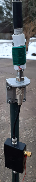
The picture shows the essential elements of the finalized CLEFHW. At the top, out of the picture, is the stainless steel, telescopic whip.
The coil was wound with #20 insulated, solid copper wire on a short length of 1/2-inch schedule 40 PVC tube. A 3/8×24 coupling nut was inserted at the top of the tube to accommodate the whip.
At the bottom of the tube I inserted a 3/8×24 bolt and nut with sufficient thread protruding to securely fit into a CB mirror mount.
A short length (about 6 inches) of RG-58 coax with a PL-259 plug on one end and a BNC plug on the other end connects the whip/coil assembly to a small plastic project box containing the 49:1 impedance transformer.
The short counterpoise wire hangs from the connector on the side of the project box.
A quick note about the 49:1 transformer. A popular way to wind this is in the form of an autotransformer in which the ground side is common to both the primary and secondary windings. I chose an alternative method in which the primary (2 turns) and the secondary (14 turns) are separate windings. The primary is wound over the center of the secondary. The diagram above illustrates this winding method.
An advantage to this winding arrangement is that the counterpoise can be a controlled length (approximately 0.05 wavelengths) instead of relying on dissipated common mode currents in the outer braid of the coax.
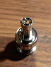
Does it work? I tested my transformer on the shack workbench using a simulated load comprising a 2K7 resistor built into a spare BNC connector.
I am not aware of any method of determining the actual impedance of an EFHW antenna erected in the field. Each installation is likely to be different so choosing a 2K7 resistor is a wild guess that is likely to be in the ballpark (at least of the R component of the impedance. Assuming the antenna is resonant, the X component should be negligible). My RigExpert antenna analyzer showed an acceptable SWR so the antenna is ready for Outback (out in the backyard) final testing.
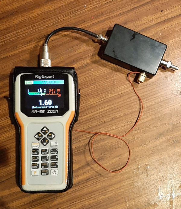
I put everything together outside. The weather at my home QTH has been typical for this time of year; temperature hovering around freezing and precipitation varying between snow, sleet and freezing rain. I grabbed an opportunity between periods of sleet to rush outside with my complete backpack station, erected the CLEFHW, hooked up the RigExpert and … another sleet shower came down. Fortunately RigExpert provides a nice protective cover for its antenna analyzer that protects it from light moisture so I went ahead with the test.
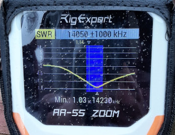
The spots on the screen are winter weather!
As can be seen in the accompanying image, the CLEFHW shows a very good SWR over the entire 20m band. I was a little concerned that this might end up as just another interesting, but failed, experiment but the results suggest I’ll be using this antenna for field operations very soon (weather permitting). I anticipated that using a loading coil would raise the Q-factor and lead to a narrow useful bandwidth, but as we see, that is not the case.
I am quite encouraged by how ideas for backpack portable operations are coming together. The real test for the CLEFHW will come when it is taken out for a POTA activation. I will report back when that happens.
Ham Radio Outside the Box is taking a break
This is the final post for 2024. The next couple of weeks are family time as we celebrate the Christmas and New Year season together. I want to thank all my regular readers for subscribing and following along with my sometimes very strange ideas. I have been humbled by just how many new subscribers Ham Radio Outside the Box has attracted this year. It seems almost every day I receive notifications of at least one new subscriber. I am especially grateful to those who syndicate this blog and help spread the notion that maybe we shouldn’t just accept the “standard” way of doing things. Taking a step sideways, rethinking and re-imagining old ideas leads to better understanding of this wonderful hobby of ours. A merry Christmas and happy new year to all.
Help support HamRadioOutsidetheBox
No “tip-jar”, “buy me a coffee”, Patreon, or Amazon links here. I enjoy my hobby and I enjoy writing about it. If you would like to support this blog please follow/subscribe using the link at the bottom of my home page, or like, comment (links at the bottom of each post), repost or share links to my posts on social media. If you would like to email me directly you will find my email address on my QRZ.com page. Thank you!
The following copyright notice applies to all content on this blog.

This work is licensed under a Creative Commons Attribution-NonCommercial-NoDerivatives 4.0 International License.
Discover more from Ham Radio Outside the Box
Subscribe to get the latest posts sent to your email.

Relatively recently I discovered your texts and have become a loyal follower. Your work is an essential help to me. Thank you.
LikeLike
Thank you for your very kind comment.
LikeLike
Hi John,
I wonder if one small modification might be to fit a case mounted PL259 plug on your UNUN box, so that it could be fastened directly under the antenna mount and hence remove the 6″ of 50ohm coax where the impedance is probably 50x as high.
Another suggestion from my experience is to have more counterpoise wires. My go-to specification is 8 3 metre long lengths of hook-up wire. Of course that is then another couple of minutes set-up time, but I find it is often worth it.
73 Ed DD5LP.
LikeLike
Thanks for the feedback Ed. I had considered attaching the UNUN directly to the antenna mount but I didn’t have a suitable panel mount PL-259 for the UNUN box. I did a quick search this morning and I see that Ali Express carries them. It shouldn’t be too important since the shield of the 6-inch coax is not connected at the UNUN so the coax becomes simply a 6-inch extension of the whip. There is one thought that your comment brought up though. The shield of the 6-inch coax IS connected at the whip end and there is an electrical path to the aluminum backpack frame. That results in a 30pF capacitive connection to the backpack frame which, in turn, has a small capacitive connection to ground. SInce the two capacitances are in series the overall impact should be negligible.
LikeLike
Nice one John.
From the pictures it looks like the orientation is vertical. So the question I have is: how does the CLEFHW compare against a quarter wave vertical mounted over a good ground plane? The whip lengths are comparable.
Of course, a “good” ground plane is not always easy to come by, especially in the field.
Merry Christmas!
de W6CSN
LikeLike
Thanks for the question Matt. The radiation pattern should be the same omnidirectional, low elevation as a quarter wave vertical. Keep in mind this is a half-wave vertical antenna that is electrically shortened by the base loading coil. That brings 2 advantages over a quarter wave vertical: first the high current point is higher up the antenna than a quarter wave thereby reducing ground losses. Second, no ground plane is required at all. The feedpoint is a high voltage/low current point so all that is required is a 0.05 wavelength counterpoise wire to dissipate the very small common mode current.
LikeLike
Hello John, I’ve made such an endfed for the 60m band a while ago. Although I used a coil at the center because a coil at the bottom gives more losses. The antenna worked but the efficiency was not that good, it was a big compromise. Have you ever thought about lineair loading your endfed? 73, Bas
LikeLike
Thanks for that idea Bas. I will look into it. That may be a good project for the new year.
LikeLike
Good evening John, first of all thank you for your posts, very interesting.Regarding the CLEFHW I was wondering how it behaves in the bands in harmonic relation, in this case the 10m.In my experience EFHW are very good antennas especially for /P use; I used them on my last vacations in IH9 and IF9, ‘dxspedition holyday style’ with very good results.TNX again, I will continue to follow your posts.
LikeLike
Thanks Vittorio. I haven’t tried it on 10m yet but the CLEFHW should theoretically behave in the same way as a full length wire EFHW. To get the best performance though, I would probably shorten the whip to a half-wave on 10m, bypass the loading coil and use the antenna as a standard vertical 10m band EFHW.
LikeLike
New to the hobby but US Navy trained in electronics 30 years ago. Finally got my ticket (KO6HAX) and your work inspires me greatly! Do you have a link to the whip antenna you are using? I really look forward to reading more of your work – and trying it out!
LikeLike
Thanks and welcome to the hobby! I bought the whip 2 or 3 years ago from AliExpress. I did a quick search and found a 5.6m (18ft 3in) whip but it has an M10 thread instead of the standard 3/8×24. Mine came with an adapter. You could substitute a 17ft whip available from several sources in the US, and increase the coil inductance. Another way to do it is hang a 18.5ft wire from a fishing pole.
LikeLiked by 1 person