The 40 meter band can be a tricky one for backpack portable operators. The problem is that antennas for that band tend to be large and require a tall pole. In the last post we discussed using a backpack as a support for quarter wave whips or short poles. In that role it is gravitationally stable, but asking a humble backpack to provide a stable base for a taller pole, say 30 feet, is unrealistic.
Ok John, but have you considered …
Loading Coil? You might argue that the same telescopic whip used for a backpack supported 20m antenna could also be used on 40m – or any other band – if it is used with an adjustable coil. Quite so, but adjustable coils (for example the popular Wolf River brand) are quite bulky and my backpack is already well stuffed with gear and becoming a little heavy.
Screwdriver? I do own a 60-years old Webster Bandspanner manual screwdriver antenna that will tune any band from 80m on up. It is a testament to the quality of the build that this antenna still works admirably well. However, the Webster Bandspanner was designed for mobile operating, mounted to a vehicle. It is quite large – too large for dragging along a hilly, rocky trail and bushwhacking through dense undergrowth.
Rybakov? One of my all-time favorites is the Rybakov antenna – but it requires a tall pole and a tuner. I will continue to enjoy using my Rybakov, but not while I am on a backpacking operations outing.
NVIS? What about a simple wire dipole or End-Fed Half Wave (EFHW)? These can erected very quickly and easily with only a short support pole. The radiation pattern is NVIS (Near Vertical Incidence Skywave) on 40m and that limits the range to just a few hundred kilometers. NVIS is a great idea for some applications, but maybe not for activities like POTA.
So what’s the solution?
I asked myself that very question. How can you go about building a field expedient portable antenna for the 40-meter band that is backpack friendly and low profile?
The solution is not new – in fact it is very old; as old as radio technology itself. It is called the “T-antenna”. The “T” could have stood for Titanic – the ill-fated ship that used this antenna for sending its distress calls by means of the original Marconi wireless equipment on board back in 1912. But the truth is the name came from the shape of the antenna.

Could a replica of Titanic’s giant antenna, downsized for the 40-meter band, be an effective ham radio antenna 112 years after Titanic slipped beneath the frigid waters of the North Atlantic? I decided to find out.
South Canadian?
Duck Duck Go found several links to information sources for T-antennas. Wikipedia provides a detailed account of the theory but the most interesting link for me came from the South Canadian Amateur Radio Society (the South Canadian is a river in Oklahoma). SCARS member Conrad W7WLM was looking for “a compact antenna that packs a big punch while using a small amount of real estate”. That sounds just perfect for my 40m backpacking antenna and so the Titanic 40m Field Expedient Backpack Portable Antenna was born.

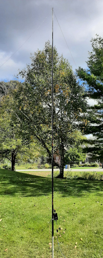
The Ham Radio Outside the Box version deviates from a traditional T-antenna in one respect. The horizontal element (a capacitive top hat) is usually flat, but I needed to use only one support so I modeled the “Titanic” with an inverted-V top hat instead. In order to bring down the SWR, the top hat wire had to be lengthened a little. W7WLM’s version recommended a top hat length of 27 feet. My version ended up at 28 feet.
Note that the vertical element is only 12 feet tall! A quarter wave whip for 40m would be around 33 feet tall – and yet the T-antenna is reported to be only slightly less efficient than a full length quarter wave antenna. This is perfect because the “Titanic” can be supported on my 14ft ultra-light crappie pole and the pole can be supported by my backpack.
A very short radiating element results in a lot of capacitive reactance at the feedpoint which is reduced by the capacitance between the top hat wire and ground. If the top hat wire does not provide enough capacitance to cancel the base reactance, the radiating element must be loaded with a coil at its base to make the antenna resonant.
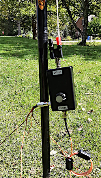
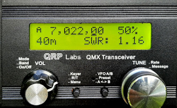
I have the perfect device for providing this base loading. It is the variable inductor from a “Miracle Whip” antenna (no longer in production). It is only suitable for QRP but it is extremely lightweight and compact enough to slip into a pocket in my backpack. This device got the job done. I measured the SWR at the end of a 25ft coax using my QRP Labs QMX transceiver (see image below) at 1.16:1.
Despite its low height to the ground the “Titanic” has a radiation pattern very similar to a full length quarter wave vertical. It is omnidirectional with a fairly low take-off angle suitable for snagging long-distance contacts, but there is also sufficient higher angle radiation to provide good mid-range coverage too.
Construction of the “Titanic”
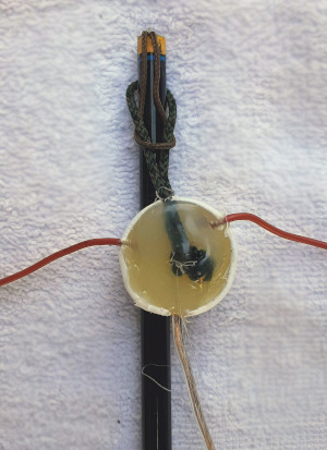
Construction could hardly be simpler. Three wires were cut; 2 x 14ft wires for the top hat and 1 x 12ft wire for the radiating element. All three wires were soldered together and potted inside a small plastic water bottle cap using hot-melt glue. I used a slightly heavier gauge wire for the radiating element because it carries quite a high current. A small loop of thin cord was also hot-melt glued into the wire junction. The top of my pole has a similar small loop of thin cord. Mounting the antenna to the pole is accomplished by threading the antenna’s loop through the pole’s loop and slipping it over the top of the pole. This simple arrangement makes it very quick and easy to mount and dismount the antenna.
A Question from the Skeptic-in-Chief
“Never believe everything you read on the Internet”
- Abraham Lincoln
I am probably the biggest skeptic of my own ideas. Something struck me as not quite right about this antenna. Why not just use a 12ft radiating element with a loading coil and forget about those fancy guy wires you call a top hat?
I asked myself this question, decided it was a valid inquiry and tried it to find out. I erected a 12ft vertical wire with the same “Miracle Whip” variable inductor used as a base loading coil and kept the same four 13ft ground radials. My Rig Expert antenna analyzer was hooked up through the same length of coax (25ft). I then approached what was now a simple base loaded short vertical whip antenna and adjusted the inductance on the Miracle Whip inductor. Yep, the SWR shot right down below 2:1 as I adjusted the inductance. But then …
The SWR was not stable. The Rig Expert reading flicked up and down. The SWR swung wildly as I moved my hand near the inductor, or if I stepped to one side. I was part of my own antenna – well it’s always nice to be a part of something – except antennas!
After restoring the top hat wires the antenna resumed normality. The SWR remained perfectly stable and my own skepticism was dispelled.
The Ham Radio Outside the Box “Titanic” 40m antenna is now ready for field testing. Let’s hope we get the same amazing results as W7WLM.
WARNING – It would be tempting fate to use the “Titanic” antenna for Maritime Mobile operations!
Help support HamRadioOutsidetheBox
No “tip-jar”, “buy me a coffee”, Patreon, or Amazon links here. I enjoy my hobby and I enjoy writing about it. If you would like to support this blog please follow/subscribe using the link at the bottom of my home page, or like, comment (links at the bottom of each post), repost or share links to my posts on social media. If you would like to email me directly you will find my email address on my QRZ.com page. Thank you!
The following copyright notice applies to all content on this blog.

This work is licensed under a Creative Commons Attribution-NonCommercial-NoDerivatives 4.0 International License.
Discover more from Ham Radio Outside the Box
Subscribe to get the latest posts sent to your email.

Hi John
I tried a similar Tee Antenna but used the Chameleon coil and used 6 ft for the vertical and top wires but it didnt seem to be that great. I will try with longer wire lengths.
I was looking for a DIY Traveller antenna but its not backpackable unless I use my Buddipole parts but again I think the wire lengths I used were too short
John VE3IPS
Parks, Antennas, Poor Weather = FUN
LikeLike
Hi John. Let me know if you do try it again. A 6ft radiator and 6ft top wire are the recommended lengths for 20m. I figured most antennas for 20m are compact enough already so I haven’t tried a T-antenna for that band. Best wishes to all at YRARC. 73
LikeLike
I just tried it on 40m to compare to an inverted -v and did not even think of the other bands during a few activations. I woke up one night in a panic and it gave me a chance to wonder if all this set up time is worth it? I can use simpler compromise antennas and not go for something complicated. It needs more experimentation and of course I will deploy it when its cold. I had misplaced a 20m EFHW and wanted to try it with the drive on mount for a 33 ft mast and it was -20 windchill. Next time I came out to work Europe from the park on 20m SSB I used a vertical stuck in the snow with 4 radials….faster easier and seemed worked just as good. Both days got me 3 EU contacts but with 2 different antennas….which antenna is better? Only Marconi may know
LikeLike