To start, let me define what I mean by “manpack”. My manpack is a manually transportable, rapidly deployable, field expedient complete radio station for operating while pedestrian mobile or pedestrian stationary .
The HFpack group of /PM enthusiasts are the experts in operating Pedestrian Mobile. Personally I prefer the Pedestrian Stationary style of operating. The terrain in which I operate is usually characterized by dense trees and low power lines (which are often concealed by trees). It just simply isn’t practical to wear a backpack supported vertical antenna. Another reason for preferring stationary ops is that I am a CW operator and my keying resembles QLF (an old CW joke: “are you sending with your left foot?”) when I am comfortably seated, never mind while trekking through the bush.
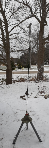
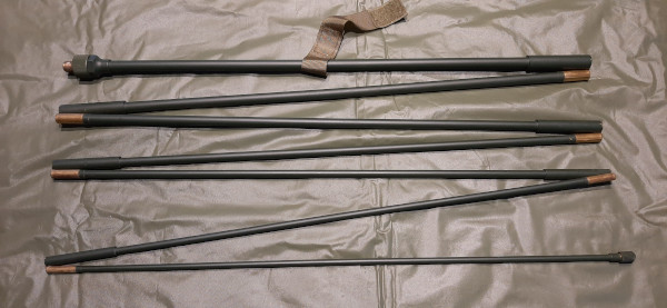
After having read articles by several enthusiasts using mil-surplus Clansman PRC-320 and similar manpack radios, I wanted to try to build my own lighter weight version so I ordered a tactical 9.5 feet whip antenna from Amazon. These antennas are 7-section HF whips held together with shock cord. They are very fast and easy to erect; simply lay them down and shake lightly; all the sections spring together like magic.
The PRC-320 comes with a 2.4-meter whip intended for short-range (~30km) ground wave comms but can also be deployed with a dipole for long-range sky wave operations. That sounded like the kind of operational agility I wanted to emulate.
There are a couple of issues with having an antenna mounted directly on the radio like the PRC-320. First and foremost is RF exposure which may be significant and dangerous unless RF power is kept to QRP level. But, a short whip is an inefficient antenna so its range may be limited at low power. Secondly, antenna tuning will be affected when in close proximity to the operator.
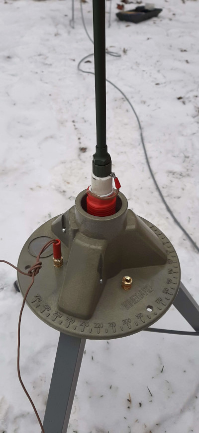
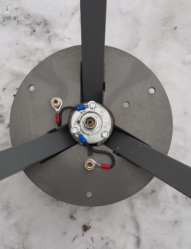
In the summer I would simply mount the whip on a spike stuck into the ground, but since it is winter I modified an old Winegard satellite dish tripod to support the antenna. In the pictures you can see the 3/8×24 mount and the connections for radials. The tripod sits at the end of a 10-foot coax so, even when I am operating at “QROp” (20 watts) power there is no RF exposure to worry about.
My bought and paid for QRP Labs QMX radio won’t be delivered anytime soon [grumble and groan]. In the meantime, for operation with my current favorite QRP rig, a Hendricks PFR-3, I built three loading coils; one each for the supported bands of 20m, 30m and 40m. No loading coil is required for 17m, 15m, 12m and 10m when I am using my all HF bands Yaesu FT-891 with an LDG Z-11 Pro autotuner.
The loading coils are interchangeable, although a band change involves dismantling the antenna. I was willing to accept slow band changes in exchange for the improved loss compared to a single coil with selectable taps.
Each coil slips over an inner coil former made from 1/2-inch PVC plumbing pipe. The coils are wound on plastic tubes cut from toilet paper roll holders; they fit very snugly! The inner former has a female 3/8×24 end for mounting the whip and a male 3/8×24 end for screwing into the tripod. The female end is a standard coupling nut. These come in different sizes so I found it necessary to apply a layer of shrink wrap to mine and then epoxy glue the coupler into place to ensure it firmly supports the whip. The male end is a 3/8×24 nut and bolt which didn’t quite fit inside the PVC pipe, but heating the end of the pipe with a heat gun softened it sufficiently to let the nut and bolt slide inside. When the pipe cooled it gripped the nut and bolt very tightly.

The coil inductances were determined using an online calculator at 66pacific.com. For the 20m coil a very low 2.8 microhenries was required and that created some difficulty. I discovered the inductance varied depending on how well the coil turns were compressed and how much stray inductance was introduced by the end connections. Even a very small variation in the order of 0.2 microhenries made a big difference in where the resonant point appeared on a Smith chart. Such is the nature of using a very short whip with a loading coil.
So what kind of performance can be expected from this antenna? That is hard to predict because we are approaching a solar cycle maximum and propagation conditions are considerably improved over even a couple of years ago. So far I have QSOd on the 20m version. In fact I was hunting CW POTA stations with my QRP rig and received a 579 report from a station in Florida over 1500km (980 miles) away. I guess that beats out the PRC-320 specification of 30km. But, it should be noted, although my whip is similar in construction to that of the PRC-320, it is slightly longer; closer to 2.9 meters instead of 2.4 meters for the ex-military rig. I also suspect that the 30km range quoted for the PRC-320 was probably for phone, whereas I used CW mode. Five watts CW is often compared to 100 watts sideband for signal range.
A 9.5ft whip is very short, even on the 20m band, so although it can be resonated on the lower bands by means of loading coils, it is going to have a high Q and hence narrow bandwidth. An EZNEC model shows it should be usable throughout the bottom CW portion of the band where I usually operate, so I can be optimistic about its performance while propagation conditions are on the upside.
For comparison, some amateurs have reported success using the excellent Elecraft AX1 short whip antenna. The AX1 has a whip length of only 45 inches and has coils for operating on 40m, 20m, 17m and 15m. A couple of notes from Elecraft’s website are pertinent here. The product description begins: “You’ve just crested the hill…the view is amazing” – a clever marketing ploy suggesting you shouldn’t expect too much if you aren’t on top of a hill? Also: “Resonant frequencies may vary +/- 300 kHz or more due to changes in terrain, body capacitance, and antenna height” – that’s good advice that also applies to the manpack antenna described in this post.
Finally, a vertical whip antenna requires a counterpoise or radials to provide “the other half”. Since this is intended to be a field expedient, rapid deployment antenna a big radial field isn’t practical. My counterpoise is a 33ft wire with a banana plug on one end and another in the center. For 20m, the center plug is used so that the counterpoise is deployed as two 16.5ft radials spread out on the ground. I orient these wires about 45 degrees apart and to the south (where most of my contacts will originate). For 30m and 40m the entire length of the counterpoise is used – again oriented south. Efficiency could be improved by raising the counterpoise off the ground – the length is resonant on 20m and 40m (and can be shortened for 30m) but raised counterpoise wires are rarely practical for field radio operations. Laying the wires on the ground detunes them, but works. Field radio operators are more interested in making contacts than achieving antenna perfection!
As always, your comments and suggestions are most welcome.
To come: my two main field radios – manpacked and ready to go; we start with the QRP rig in the next post.
Help support HamRadioOutsidetheBox
No “tip-jar”, “buy me a coffee”, Patreon, or Amazon links here. I enjoy my hobby and I enjoy writing about it. If you would like to support this blog please follow/subscribe using the link at the bottom of my home page, or like, comment (links at the bottom of each post), repost or share links to my posts on social media. If you would like to email me directly you will find my email address on my QRZ.com page. Thank you!
The following copyright notice applies to all content on this blog.

This work is licensed under a Creative Commons Attribution-NonCommercial-NoDerivatives 4.0 International License.
Discover more from Ham Radio Outside the Box
Subscribe to get the latest posts sent to your email.

One thought on “Building a Manpack – Part 1, the Antenna”