I have spent many hours in my reclining thinking chair, posting ideas on the back of my eyelids while contemplating this very question. How indeed does a Ground Tuning Unit (GTU, aka Artificial Ground) actually work? I have a fairly reasonable comprehension of the theory behind antenna tuners, but tuning an entire planet? Now that’s a different matter! Well, finally I believe I have an answer. Please read on, and if you disagree, let me know in the comments.
But first, some background on why I am re-visiting the topic of GTUs. My last two park activations convinced me that spreading a set of radial wires out in a public space is not always a good idea. During one of those activations I was getting very close to securing the minimum 10 contacts necessary to validate a Parks On The Air activation. QTH was a small park with a magnificent view over a large, scenic valley. My antenna footprint was a square section of uncut grass, about 20 feet wide. Suddenly, I heard a loud engine noise starting up behind me. The park maintenance crew had arrived with an enormous zero-turn lawn tractor to cut the grass!
My wife was sitting nearby “activating” one of her favorite Stephen King novels. She leapt to her feet and ran over to speak to the young lady on the lawn tractor. I had just logged contact number 9 and was concerned that I might have to abort the activation just one QSO short of the minimum. Fortunately, the lawn tractor jockey was a very pleasant and cooperative young lady who readily agreed to suspend cutting the grass until I had finished. Such a pleasure to come across such fine people.
I wrote about the second of these activations in my last post. Once again I had set up my vertical antenna with a set of radials spread around the antenna. Then along came the “that’s so cool!” woman that I wrote about previously. My wife leapt up from her chair and advised the visitor to be careful of the wires on the ground. No disrespect intended towards the inquisitive lady, but I believe I actually smiled as she did a little dance in an attempt to avoid stepping on my radials.
Both of those activations took place in small parks where available space was limited. I thought that since I was doing my activations just before the school summer break, foot traffic would be light. The parks were indeed quiet, but it only takes one person on a honking great grass cutter or just one dancing, inquisitive visitor to give me pause to rethink my operation.
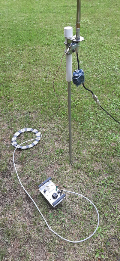
As a result, I reached into one of many vaults where I store my trove of ham treasures and pulled out my DIY GTU. Frankly, first experiments with it were a disappointment. Yeah, it kinda worked but got me thinking how I might improve it.

If you look at designs for making a GTU on the great whirled wild web a couple of things stick out. First, wind a big coil with lots of taps. Second, get your hands on an air-spaced variable capacitor with a value of around 500 picofarads. Oh yeah? Why? Perhaps those components give you the flexibility to select a wide range of resonant frequencies and – oh well, maybe one combo of L and C will get the job done.
“Ornery” I Ain’t
I am a contrarian thinker by nature. I hold the belief that if most people believe something is true, only one of them is doing the thinking. I am automatically drawn to consider the exact opposite of what the majority believe. So, I decided I needed a small coil with very few taps and a low value variable capacitor – the exact opposite of received wisdom. But, I had a good reason for that choice and it wasn’t just to be “ornery”.
Let’s Get Series
A GTU is essentially a series L-C circuit. It can be tuned by adjusting the inductance and the capacitance to obtain resonance at a desired frequency. A simple sensing circuit – also in series with the rest of the device – provides a visual display of the current flowing through the GTU. Now suppose – instead of just winding a big, multi-tapped coil and pairing it with enough capacitance to hopefully find a match somewhere – we calculate the L and C values needed for resonance on the frequencies on which we wish to operate?
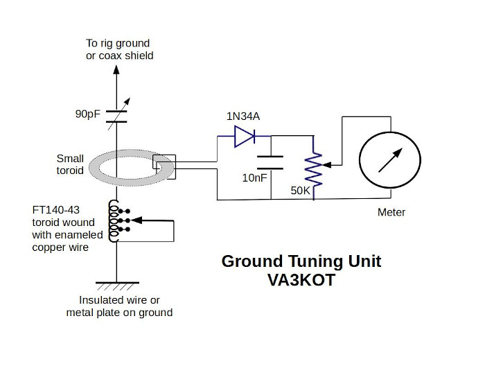
The formula involved should be tattooed into the grey matter of every ham, but there are online calculators available for those who are averse to mathemagic. I devised a LibreOffice spreadsheet and used the “Monte Carlo” method to plug in various values of L and C to come up with my design parameters.
Brushing aside the cobwebs and venturing once again into the dark, dusty vaults in my shack, I found a 12-position rotary switch. But disappointment loomed – it was a 4-pole, 3-way switch. So that limited the number of taps on my coil to three. I wound some turns of enameled copper wire on a FT140-43 toroid and measured the inductance with my trusty Almost All Digital Electronics L/C Meter IIB.
Hubble, Bubble Toroid and Trouble
If you have ever wound a toroid to achieve a specific tapped inductance you may have shared my experience that the turns between taps are interactive. There is no pF/turn ratio you can rely on. There is witchcraft involved so just wind it and measure it!
The Fine Small Gang Beats the Coarse Big Gang
One of the disappointments I experienced when messing with my Mark1 GTU design was with the variable capacitor adjustment. Following conventional wisdom I used a 365pF varicap and found the adjustment was way too coarse. The component I had installed has two gangs, one of 365pF and the other of 90pF. I figured if I use the 90pF section I will get finer control of the capacitance. It worked. My inductor ended up with taps at approximately 3, 5 and 10 microhenries. Plugging those values into my spreadsheet gave me resonance across all the bands I needed.
And Now the 64 Gigadollar Question
When using a L-C resonance circuit to match an antenna, we have a rough idea of the impedance of the antenna. For example, we know a typical dipole will be about 70 ohms, an End-Fed Half Wave will be about 2-3000 ohms. But what’s the impedance of this cosmically insignificant hunk of rock we call Planet Earth?
We know that the job of our GTU is to provide the lowest possible impedance to the current flowing to ground from our antenna. Remember, the current in the antenna must be equal to the current flowing through the “other half”. A quarter wave vertical antenna can be thought of as a vertical dipole where the other half is a mirror image in the ground.
So what is the impedance of the ground? Well of course it is ideally zero ohms i.e. a perfect ground. In practice the ground is never perfect and that is why some antenna installations are less efficient than others. If we all lived by the sea we could be assured of a good (but even then, not perfect) ground since salt water is a good electrical conductor. I live 800km from salt water, on the Niagara Escarpment where the ground has good conductivity mainly because nutrient-rich rainwater gets trapped in a thin layer of soil above solid ancient rock.
So, in conclusion, a Ground Tuning Unit maximizes the current in the “bottom” half of an antenna system which results in a correspondingly higher current in the top half. The bottom half could be the Earth itself, or in the total absence of a real earth ground (for example on the upper floor of a home) a length of wire.
If you have other thoughts on the topic, let me know in the comments below.

Do you really need to isolate the antenna from the support pole with PVC pipe since you ground the antenna anyway? (Yes, I’m fairly new to the hobby, couple years or so.) Thanks KF0GPX
LikeLike
Thanks for the question Monty. No, it isn’t strictly necessary to isolate the antenna from the support pole. I did this to ensure all the ground current would flow through the GTU. If the ground current found any other route I could not be sure my GTU was doing its job. During normal operation I allow a direct path to ground through the support pole. This path is a very Inefficient RF ground so I can still be sure that most of the ground current is passing through the GTU.
LikeLike
Thank you for your reply! KF0GPX
LikeLike
John, You should look into having the GTU you designed produced commercially for sale either on your own site or Ebay.
LikeLike
Thanks for the idea Gary but GTUs are already commercially available, for example, the MFJ-931. Other hams, e.g. VK3YE and G4AKC have also written about or produced videos on the topic. My design differs in some details from others but my intention in this post was to analyze how a GTU works. I appreciate your feedback.
LikeLike
I have used an MFJ-931 Artificial Ground to good effect in my 2nd floor condo station. I have no access to anything other than the 3rd prong electrical ground from power. My antenna is a Wolf River Coil vertical on a tripod on my balcony, with 3 33-foot radials folded around the balcony floor. I’ve worked all over the world with this antenna.
I attribute at least part of the remedy of my RFI issues to my 931. Along with judicious use of Mix31 toroids on every cable, the artificial ground was needed to put me over the top on eliminating 99% of RFI in the shack.
I do wonder how much current actually flows in the ground circuit (the meter indicates peak but is not calibrated to show the actual magnitude of the current).
I also wonder about the source of the current. Yes, the “ground” is the bottom half of the antenna, but I wonder how much is from common mode current and/or induced from the actual radiated signal (since the antenna is only about 10 feet away from all the station equipment).
I think these devices are often overlooked by many hams and could help improve their station (of course everyone’s mileage will vary).
You can also use a “poor man’s” artificial ground and cut 1/4 wave wires for every band of interest and attach to the station ground, leaving the far end of the wire dangling (open).
LikeLike
Thanks for the feedback Marlo. You made a good point about other current sources on the ground wires. Working from a condo balcony must be very challenging but you seem to have made a success of it.
LikeLike
Since antenna radiation is related to antenna current, and, as you said, increased ground current results in increased antenna current…does it not follow that a GTU should increase transmitted energy? Texts suggest that vertical antennas should have many radials …why not just one ground tuner device? I guess I don’t understand.
David Gauger
W9CJS@ARRL.NET
LikeLike
Thanks for the comment David. I agree, a large radial field is the ideal solution and that is the route I would take for a permanent installation. But when I need a field antenna that is set up and taken down maybe an hour later, I use either 4 ground radial wires or the GTU. Adjusting the L and C values in the GTU affects the SWR and hence the amount of RF that is radiated rather than wasted as heat. In that way the GTU may even provide a better “other half” solution than 4 radial wires which are a compromise between convenience and efficiency.
LikeLike
Hello John, I found your article very interesting and relevant as I’m putting together an FT-891 Go Kit and want to add a ground tuning unit. I have my 500pF tuning capacitor at the ready but it’s a big brute and space is limited. I turned down the offer of an MFJ GTU because of its size. Please tell me more about the random coil of shorted coax – is this shorted core to screen at one end, both ends, or is the outer insulation stripped off and the braid touching all the way along like a thick disc? 73 de John G4EDX
LikeLike
Thanks for the question John. It is not important how the coil of coax is shorted since the braid provides most of the capacitance to ground just make sure the coax braid has a connection to the GTU. There are now better ways to do the same thing. For example VK3YE has used a beach mat covered with aluminum foil. In your part of the world G4AKC uses an aluminum plate. Here in Canada we use aluminum mesh screens on our windows to keep the bugs out and that material works very well. Other people have used Faraday cloth which is probably the lightest solution. Try experimenting with different types and sizes of material to see which works best for you. Let me know what you come up with.
LikeLike
Is it like a capacitance hat then, but at the other end? A capacitance sock? I’ll try coax first because I have some of dubious ancestry. Many thanks for the quick reply.
LikeLike
Hello again John, as I’m laying out my FT-891 Go Kit fittings in an aluminium frame it occurs to me that a continuously variable GTU sensitivity control might not be the best option. Instead of a variable resistor I’m going to use a rotary switch and a set of resistors giving me times two increments in sensitivity. The tapped inductor will also be on a rotary switch, and the tuning capacitor will be the only continuously variable variable, if you see what I mean. That way I can change the ground lead and whatever is attached to the end, and make direct comparisons of ground current, switching ranges if necessary. Any thoughts, please?
LikeLike
I’m always in favor of experimentation but the switched resistors in the sensing circuit may be an over-complication. The sensing circuit is a useful guide to finding the maximum ground current but it’s not a critical part of the circuit. Adjusting the GTU affects the antenna SWR so I sometimes don’t even look at the meter on the GTU. Try your switched resistor idea and see if it works for you. The critical part of a GTU is the series L-C circuit; you need to design that very carefully otherwise you may find it difficult to adjust for peak ground current. I see you are starting your own blog, maybe you could document your GTU and your FT891 go-kit there. I’ll subscribe when you get it up and running. Good luck John.
LikeLike
It’s all theory at the moment of course, but I thought that having switched ranges might help me evaluate different ground options at the same time and location, for example ground spike, ground mat and counterpoise.
I see that your GTU uses a ferrite toroid for the switched inductor. VK3YE uses a T68-2. I have a few rotary switches so I could wind one coil on iron dust and one on ferrite and swap them quite quickly for comparison.
I’ve always been puzzled that shorten turns are a bad thing in power transformers but don’t seem to matter in RF coils. Have you tried your coil with and without shorting the unused part?
Finally, the blog. No, I didn’t intend to start one. I tried to send my first message to you just by email but that didn’t seem to work. I tried to sign up for WordPress (is it?) and found that I’d already joined. It must be years ago because I’d forgotten. I even found my old username. If I make good progress with this I might write it up as a blog. That’s a little way off.
I finished printing the plate to hold the tuning capacitor, rotary switches and binding post last night and fitted it this morning. I just need to find the shaft coupler, or turn a new one, and use part of a rotary switch spindle for the tuning capacitor. Then wind the coil.
LikeLike